-
Welcome to Tacoma World!
You are currently viewing as a guest! To get full-access, you need to register for a FREE account.
As a registered member, you’ll be able to:- Participate in all Tacoma discussion topics
- Communicate privately with other Tacoma owners from around the world
- Post your own photos in our Members Gallery
- Access all special features of the site
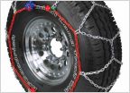 Chain Recommendation's?
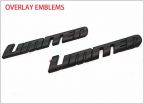 Gloss Black Tacoma Limited Emblem
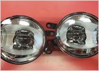 Fog light problem
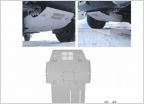 KUAFU Skid plate?
 Bed Extender 3rd Gen vs 2nd
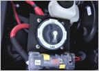 Winches and pumps
Lateralis '17 BPP build
Discussion in '3rd Gen. Tacomas (2016-2023)' started by Lateralis, Oct 2, 2018.