

-
Welcome to Tacoma World!
You are currently viewing as a guest! To get full-access, you need to register for a FREE account.
As a registered member, you’ll be able to:- Participate in all Tacoma discussion topics
- Communicate privately with other Tacoma owners from around the world
- Post your own photos in our Members Gallery
- Access all special features of the site
 Sirius for 09 Tacomoa factory sat radio
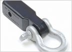 Recovery Straps
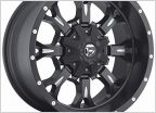 Would this 17x9 fuel krank wheel fit my stock TRD off road 2015 tacoma?
 4.0L V6 Cold Start Engine Knock, Noise, Possible Cause ???
 Squeaking/Grinding Sound Starting in 1st 6MT
 P0430 Code
Warn Winch cab switch install question
Discussion in '2nd Gen. Tacomas (2005-2015)' started by 000doodie000, Dec 20, 2018.
Page 1 of 2
Page 1 of 2


