-
Welcome to Tacoma World!
You are currently viewing as a guest! To get full-access, you need to register for a FREE account.
As a registered member, you’ll be able to:- Participate in all Tacoma discussion topics
- Communicate privately with other Tacoma owners from around the world
- Post your own photos in our Members Gallery
- Access all special features of the site
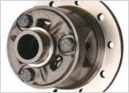 Lunchbox lockers
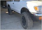 Just bought a 1999 Tacoma 4cyl 4x4
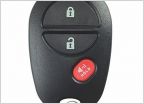 OEM Remote Key Fob Replacement: Best place to get get it?
 Power Window Diagnostic
99 SR-5 2.7 5 spd- cranks but won’t start
Discussion in '1st Gen. Tacomas (1995-2004)' started by Benjamos, Mar 14, 2019.
Page 2 of 2
Page 2 of 2