

-
Welcome to Tacoma World!
You are currently viewing as a guest! To get full-access, you need to register for a FREE account.
As a registered member, you’ll be able to:- Participate in all Tacoma discussion topics
- Communicate privately with other Tacoma owners from around the world
- Post your own photos in our Members Gallery
- Access all special features of the site
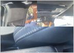 Headliner rattle and other general rattles
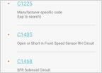 ABS, Traction control and Brake warning lights
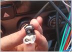 What cables are these (head unit)?
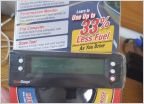 Where are you guys mounting your Scangauge?
 A couple of new things...
 Toyota Techs don't f**ck around!
Nitori's OEM SR Foglight mod!
Discussion in '3rd Gen. Tacomas (2016-2023)' started by Nitori, Sep 17, 2016.
Page 12 of 46
Page 12 of 46
Products Discussed in


