

-
Welcome to Tacoma World!
You are currently viewing as a guest! To get full-access, you need to register for a FREE account.
As a registered member, you’ll be able to:- Participate in all Tacoma discussion topics
- Communicate privately with other Tacoma owners from around the world
- Post your own photos in our Members Gallery
- Access all special features of the site
 Small cup holders
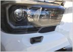 Retrofit Headlight Washer Jet on Tacoma
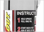 Best auto fire extinguisher?
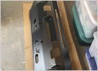 3rd Gen 4XInnovations Front Bumper Install With Pictures (2016+)
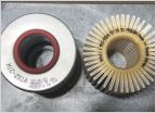 PSA: Mobil1 M1C-251A filter has changed.
Dual Battery Fuse/Breaker Layout
Discussion in '3rd Gen. Tacomas (2016-2023)' started by RedZeppelin, Jan 28, 2020.

