

-
Welcome to Tacoma World!
You are currently viewing as a guest! To get full-access, you need to register for a FREE account.
As a registered member, you’ll be able to:- Participate in all Tacoma discussion topics
- Communicate privately with other Tacoma owners from around the world
- Post your own photos in our Members Gallery
- Access all special features of the site
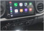 After market stereo for 2020 TRD Off Road
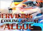 Transmission The new 6 speed AC60 Series automatic in the 2016 " WRITE UP WITH PICS
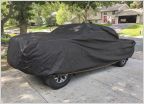 Car cover
 Oil Change
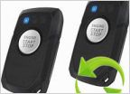 Installing an Ignition Bypass Switch for Warm-Up
 A guide on how to separate your headlights for BHLM or projector upgrade
Getting ready to start my wiring. Any suggestions?
Discussion in '3rd Gen. Tacomas (2016-2023)' started by Puppypunter, Jun 25, 2020.
Page 1 of 2
Page 1 of 2


