

-
Welcome to Tacoma World!
You are currently viewing as a guest! To get full-access, you need to register for a FREE account.
As a registered member, you’ll be able to:- Participate in all Tacoma discussion topics
- Communicate privately with other Tacoma owners from around the world
- Post your own photos in our Members Gallery
- Access all special features of the site
 SoCal 4x4 Shop Good at Electrical
 Sharkfin antenna - completely abandon and upgrade
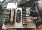
 Pigtails, plugs, and where to find them
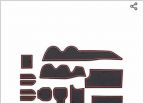 Rubber dash inserts
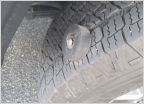 Picked Up A Screw (tire thread)
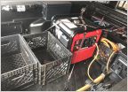 Cargo thingy....
M LED 2.0 Retrofit and TRD Headlight to SR Conversion
Discussion in '3rd Gen. Tacomas (2016-2023)' started by kmorgan3, Dec 3, 2020.
Page 1 of 2
Page 1 of 2


