

-
Welcome to Tacoma World!
You are currently viewing as a guest! To get full-access, you need to register for a FREE account.
As a registered member, you’ll be able to:- Participate in all Tacoma discussion topics
- Communicate privately with other Tacoma owners from around the world
- Post your own photos in our Members Gallery
- Access all special features of the site
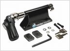 Need solution to lock bicycle to open truck bed
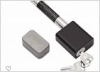 Hitch Pin Lock Recommendations?
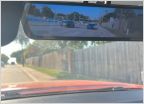 Rearview camera installation
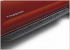 Cast Aluminum Running Boards
 Battery issue or what?
 Bed mounted ez up canopy?
Heated Seats Help
Discussion in '3rd Gen. Tacomas (2016-2023)' started by IMAsaltedPretzel, Dec 8, 2021.


