

-
Welcome to Tacoma World!
You are currently viewing as a guest! To get full-access, you need to register for a FREE account.
As a registered member, you’ll be able to:- Participate in all Tacoma discussion topics
- Communicate privately with other Tacoma owners from around the world
- Post your own photos in our Members Gallery
- Access all special features of the site
 Woody's Quicksand Build
 Clean, Purpose-Built 3rd Gen SR5
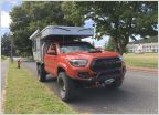 Stu’s UTE
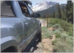 MTNHABT Overland Adventure Rig, Build Thread!!!
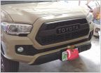 Wife said buy a mini van
The Ugly Blue Truck - Now With Feeble Attempts at Remapping Volume/Seek Buttons!
Discussion in '3rd Gen. Builds (2016-2023)' started by BudFriendguy, May 24, 2021.
Page 3 of 5
Page 3 of 5

