

-
Welcome to Tacoma World!
You are currently viewing as a guest! To get full-access, you need to register for a FREE account.
As a registered member, you’ll be able to:- Participate in all Tacoma discussion topics
- Communicate privately with other Tacoma owners from around the world
- Post your own photos in our Members Gallery
- Access all special features of the site
 PIAA 510 Fogs and Hella backup lights installed
 SPod or Switch Pro
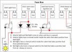 New Truck - DIY light wiring second opinion
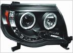 Headlight advice
 KC CYCLONE V2 color demo
 3rd gen Headlight bulb question
Help w/ 3-way switching
Discussion in 'Lighting' started by jsackspot, Jul 10, 2022.


