

-
Welcome to Tacoma World!
You are currently viewing as a guest! To get full-access, you need to register for a FREE account.
As a registered member, you’ll be able to:- Participate in all Tacoma discussion topics
- Communicate privately with other Tacoma owners from around the world
- Post your own photos in our Members Gallery
- Access all special features of the site
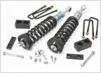 Will all of these parts work well with my 2014 base 4x4 Tacoma?
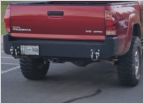 Does anyone know who makes this?
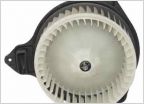 Dealer unwilling to
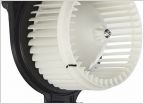 Ticking Coming From Blower Motor (Help Needed)
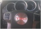 Looking for these trd center caps
2nd Gen Information & Diagnostics
Discussion in '2nd Gen. Tacomas (2005-2015)' started by Dm93, Nov 13, 2022.
Page 1 of 2
Page 1 of 2
Products Discussed in


