

-
Welcome to Tacoma World!
You are currently viewing as a guest! To get full-access, you need to register for a FREE account.
As a registered member, you’ll be able to:- Participate in all Tacoma discussion topics
- Communicate privately with other Tacoma owners from around the world
- Post your own photos in our Members Gallery
- Access all special features of the site
 Cheap, but effective LED backup lights?
 Problem!!
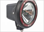 Amazon 7" 55w HID Pods - Any good?
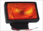 Back to the Future Toyota question??
 KC HiLiTES 801 Rally or Hella Rally 4000
 Topper 3rd Brake Light Harness/Adapter
Planning my DRL install on my first gen, requesting a once over for my circuit.
Discussion in 'Lighting' started by darth_bronchioles, Sep 20, 2023.


