

-
Welcome to Tacoma World!
You are currently viewing as a guest! To get full-access, you need to register for a FREE account.
As a registered member, you’ll be able to:- Participate in all Tacoma discussion topics
- Communicate privately with other Tacoma owners from around the world
- Post your own photos in our Members Gallery
- Access all special features of the site
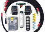 Need Wiring Help
 2017 Tacoma TRD Off Road/low profile mud flaps
 Rear Toe Out after 5100 and 1 inch ear block
 Wireless Apple CarPlay?
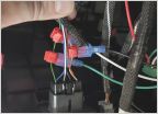 Fog Light Wiring help
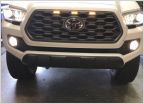 3 raptor lights on 2020 Tacoma TRD 4X4 non-Pro grille
Will this start a fire?
Discussion in '3rd Gen. Tacomas (2016-2023)' started by d0ugh0ck, Dec 21, 2023.
Page 2 of 2
Page 2 of 2

