-
Welcome to Tacoma World!
You are currently viewing as a guest! To get full-access, you need to register for a FREE account.
As a registered member, you’ll be able to:- Participate in all Tacoma discussion topics
- Communicate privately with other Tacoma owners from around the world
- Post your own photos in our Members Gallery
- Access all special features of the site
 Hard Mounting VIAIR 400P?
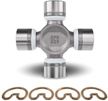
 Part numbers for ujoints
 Is the Haynes book the best "first book"?
 Shock reservoir mount options
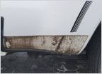 Damaged stone guard repair gen 2
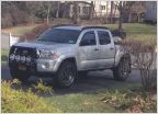 "Grill guard ideas?"
Need elec. help with the dreaded Abs, Parking, traction lights on and no speedometer,
Discussion in '2nd Gen. Tacomas (2005-2015)' started by anything, Mar 4, 2024.