-
Welcome to Tacoma World!
You are currently viewing as a guest! To get full-access, you need to register for a FREE account.
As a registered member, you’ll be able to:- Participate in all Tacoma discussion topics
- Communicate privately with other Tacoma owners from around the world
- Post your own photos in our Members Gallery
- Access all special features of the site
 Truck bed mattress
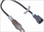 2016 Tacoma Air Fuel Sensor replacement
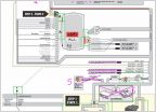 Fortin remote start with alarm
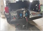 Making compressor fit
 Jack recommendation for tacoma
 GPS tracker
3rd Gen HID vs LED vs Halogen H11 projector headlights
Discussion in '3rd Gen. Tacomas (2016-2023)' started by crashnburn80, Jan 25, 2019.
Page 331 of 339
Page 331 of 339
Products Discussed in