

-
Welcome to Tacoma World!
You are currently viewing as a guest! To get full-access, you need to register for a FREE account.
As a registered member, you’ll be able to:- Participate in all Tacoma discussion topics
- Communicate privately with other Tacoma owners from around the world
- Post your own photos in our Members Gallery
- Access all special features of the site
 Denso Spark Plugs
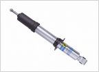 Adjustable Bilstein issues
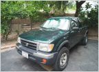 1999 Tacoma SR5 TRD Imperial Jade Build, Sweat and Tears
 Can the wrong air/fuel ratio sensor cause p0171?
 Salvaging a seal?
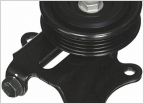 Power steering belt tensioner assembly bolt p/n 44350-34010
Custom turn signal cancellation circuit for running light
Discussion in '1st Gen. Tacomas (1995-2004)' started by HoneyBadger153, Oct 14, 2024.

