

-
Welcome to Tacoma World!
You are currently viewing as a guest! To get full-access, you need to register for a FREE account.
As a registered member, you’ll be able to:- Participate in all Tacoma discussion topics
- Communicate privately with other Tacoma owners from around the world
- Post your own photos in our Members Gallery
- Access all special features of the site
 Help a Newbie out! (Wheels)
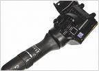 2014's intermittent wiper switch
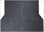 Who line-x their bed?
 Starter going bad??
 K&N Intake problem
P0420 troubleshooting sensors
Discussion in '2nd Gen. Tacomas (2005-2015)' started by Jacks2010Taco, Nov 24, 2024.


