

-
Welcome to Tacoma World!
You are currently viewing as a guest! To get full-access, you need to register for a FREE account.
As a registered member, you’ll be able to:- Participate in all Tacoma discussion topics
- Communicate privately with other Tacoma owners from around the world
- Post your own photos in our Members Gallery
- Access all special features of the site
 Off topic (sort of)
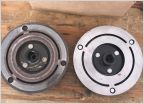 AC clutch install SUCCESS!
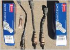 P0430 Code: Catalyst System Efficiency Below Threshold (Bank 2)
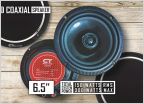 Speaker upgrade for a 2nd gen questions
 Remounting backup camera
2nd Gen Wiring Overhaul - A slow descent into madness
Discussion in '2nd Gen. Tacomas (2005-2015)' started by deanosaurus, Mar 18, 2021.
Page 6 of 6
Page 6 of 6
Products Discussed in


