

-
Welcome to Tacoma World!
You are currently viewing as a guest! To get full-access, you need to register for a FREE account.
As a registered member, you’ll be able to:- Participate in all Tacoma discussion topics
- Communicate privately with other Tacoma owners from around the world
- Post your own photos in our Members Gallery
- Access all special features of the site
 Squeaking AC with AC off?
 Stock toyota oil filter or any brand oil filter?
 Snorkel
 N-Fab Nerf Steps
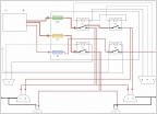 Custom Headlight Harness Build
Fixing A P0500 Check Engine Light By Re-Soldering The Instrument Cluster
Discussion in '2nd Gen. Tacomas (2005-2015)' started by Orange Dave, May 23, 2025.
Products Discussed in


