

-
Welcome to Tacoma World!
You are currently viewing as a guest! To get full-access, you need to register for a FREE account.
As a registered member, you’ll be able to:- Participate in all Tacoma discussion topics
- Communicate privately with other Tacoma owners from around the world
- Post your own photos in our Members Gallery
- Access all special features of the site
 Icon Stage 5 + ARB Bullbar Installation Report
 Suspension upgrade for loading up bed
 2015 Radio touchscreen out of calibration
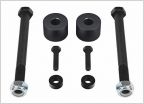 What Diff Drop Brand To Get?
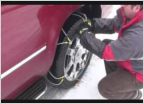 Best Snow Chains for 2014 TRD
Drive Shaft Vibrations Solved Step-by-Step
Discussion in '2nd Gen. Tacomas (2005-2015)' started by TscotR214, Oct 18, 2012.
Page 2 of 60
Page 2 of 60

