

-
Welcome to Tacoma World!
You are currently viewing as a guest! To get full-access, you need to register for a FREE account.
As a registered member, you’ll be able to:- Participate in all Tacoma discussion topics
- Communicate privately with other Tacoma owners from around the world
- Post your own photos in our Members Gallery
- Access all special features of the site
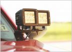 Pics Ditch Light and CB Antenna Mounts
 Matt Gecko's under hood LED lighting ket - hood switch install
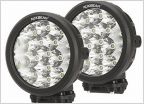 Auxbeam 2 Pcs 7" Round Cree LED Driving Light Bumper Offroad 80w 8000lm Combo beams
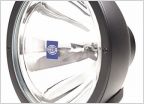 Installing lights on Bullbar
 2019 OR, XD LEDs not working
 Unlit Switches
Footwell LED add on dome circuit
Discussion in 'Lighting' started by TigerTacoma, Aug 11, 2014.


