

-
Welcome to Tacoma World!
You are currently viewing as a guest! To get full-access, you need to register for a FREE account.
As a registered member, you’ll be able to:- Participate in all Tacoma discussion topics
- Communicate privately with other Tacoma owners from around the world
- Post your own photos in our Members Gallery
- Access all special features of the site
 164,000 should I flush rear diff fluid and tran fluid?
 ARB locker issues in Cold weather
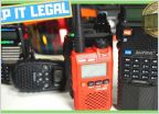 Good range handheld radios?
 Restoring trim
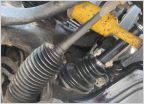 Rubber boot around tie rod leaking grease?
 Squeaking AC with AC off?
09 Tacoma DC DRL/Turn signal LED load resistor wiring
Discussion in '2nd Gen. Tacomas (2005-2015)' started by arvir, Aug 28, 2017.


