1. Welcome to Tacoma World!

    You are currently viewing as a guest! To get full-access, you need to register for a FREE account.

    As a registered member, you’ll be able to:
    • Participate in all Tacoma discussion topics
    • Communicate privately with other Tacoma owners from around the world
    • Post your own photos in our Members Gallery
    • Access all special features of the site
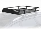
20-23 Anytime front/backup camera

Discussion in '3rd Gen. Tacomas (2016-2023)' started by bigssa, Oct 17, 2022.

  1. Oct 17, 2022 at 12:55 PM
    #1
    bigssa

    bigssa [OP] Well-Known Member

    Joined:
    Jul 29, 2022
    Member:
    #402414
    Messages:
    61
    Gender:
    Male
    Charleston, SC
    Vehicle:
    2022 MGM DCLB SR5 RWD
    [This post has been updated to reflect changes and details based on discussion in the entire thread and to simplify information for future reference]

    If you are interested in building your own anytime front/rear camera harnesses then this post may help. After looking over some videos of installations and the pictures on https://www.anytimebackupcamera.com/products/2020-kit, I thought that this would be an interesting project to put together myself. This project is relatively simple but if you are not comfortable with basic circuitry then I would recommend buying the kit. This post is not going to cover much of the installation as you can reference a good installation guide here: https://cdn.shopify.com/s/files/1/0...amera_-_Install_Instructions.pdf?v=1615938677


    First, let’s make the wiring harnesses that plug into the back of the head unit. I purchased the two harnesses from AliExpress: https://a.aliexpress.com/_mqtRmig. You will need both the 28 and 30 pins harnesses.
    The connectors and pins are described here:
    https://www.tacomaworld.com/attachments/2021_tacoma_stereo_with_nav_pinout-pdf.5203700/ and https://www.tacomaworld.com/attachments/2021_tacoma_stereo_without_nav_pinout-pdf.5203701/


    Starting with the 28 pins connector (R48 in the documents)
    - Tap into pin 15 for a 12 V source
    - Remove the wire and pins at location 16 (or any of the many other pins not in use)
    - Please note that the new recommended way is to use a relay for the reverse trigger instead of diodes. Please use this post for a reference.
    - Pin 28 will come with a red reverse trigger wire on the female end, leave that one in
    - Cut the female end of the wire sourced from pin 16 and insert the male pin at location 28 on the male connector
    - Here is a picture of mine (note that mine has the blue wire coming out of pin 28 due to the change I am making to use the relay implementation, but yours will have one side blue and one side red):
    [​IMG]


    30 pins harness (R49 in the documents) - The harness is wired for an RCA input connection but is missing the RCA output connection from the reverse camera. So you will need an RCA male connector. If you have a spare RCA cable then you can source it from there, otherwise you can buy a couple from here (you need 2 male and 2 female RCA connectors for the entire project): https://a.aliexpress.com/_mtnbCkk.
    - Remove the wires and pins from locations 10 and 11 as donors for the video pins
    - Cut each wire about two inches from the male connector and solder the exposed wire end to your +/- wires from the male RCA cable
    - Insert the positive/red wire pin from the male RCA connector to pin 28
    - Insert the negative/black wire pin from the male RCA connector to pin 29
    - Here is a picture of the harness:
    [​IMG]


    Next, we will create a harness for the button. I used this button:
    https://a.aliexpress.com/_msmKCXQ but any maintained on-off-on (SPDT) switch will work perfectly. You can also purchase the wires and connectors from this seller if you wish (I did not). This button has 7 pins and that’s what I will be describing here, but a 3 or 6 pins button works but would be wired slightly differently (you won’t need a ground wire). I used a generic 4 pins connector ( https://www.amazon.com/dp/B07DK8Q5X4) to be able to easily connect and disconnect the button as needed. Here is a diagram of how the button was connected to the connector:

    upload_2022-10-19_10-42-5.jpg


    Next, we need to wire up the video relay. you will need a 5 pin, 12v relay ( https://a.aliexpress.com/_mMPdDek). The relay will connect the positive (red) wire of our output RCA with the positive wire of either the front or rear camera based on the button selection. The negative (black) wires of all three RCA cables will be connected together all the time. And we will use the front camera button output as the trigger for the relay AND to power the front camera. Note that by default, the rear camera is selected by the relay. So even when the button is in the off position, the rear camera is technically connected, which allows it to work properly when the truck is actually in reverse. Below is the diagram to wire up the relay:

    upload_2022-10-17_15-54-8.jpg

    Lastly, we need to wire up the reverse trigger relay. We will use the same relay as above. The relay will connect the OEM reverse trigger to the head unit, but will also send a 12V signal when either the front or rear buttons are in the on position. Below is the diagram to wire up the relay:
    [​IMG]

    Finally, it is time to put it all together and create a harness that can be installed in the truck. The 28 and 30 pins harnesses each connect to the back of the head unit. You should have 3 wires coming from the 28 pins harness. The first one is a 12V that should connect to the 12V input of the switch (terminals 2 and 5) and the NO (pin 87) of the reverse trigger relay. The second is the OEM revers trigger which will connect to the NC (pin 87a) of the reverse trigger relay. And the third is the reverse input to the head unit which will connect to pin 30 of the reverse trigger relay.
    Next, the 30 pins harness should have a male and a female RCA connectors. The male connector from the 30 pins harness connects to the relay's rear female RCA connector. The female connector from the 30 pins harness connects to the relay's male RCA connector.

    Moving to the two remaining wires on the button. The ground wire connects to chassis ground. The front trigger wire connects to terminal 85 of the relay and to the power cable attached to the male RCA connector coming from the front camera (not shown in these diagrams).

    Lastly, the remaining wires on the relay. The ground wire connects to chassis ground. The front female RCA cable connects to the male RCA cable from the front camera (not shown in any of these diagrams).


    Total costs for materials:

    1. Front camera - $13 - https://a.aliexpress.com/_m0DwQHA
    2. Wiring harnesses - $27 - https://a.aliexpress.com/_m0vGHyg
    3. Switch - $8.50 - https://a.aliexpress.com/_mNmdhso
    4. Relay (2) - $6 - https://a.aliexpress.com/_mNmdhso
    5. RCA connector (2 male, 2 female) - $8.50 (https://a.aliexpress.com/_mt915lw
    6. 20 AWG wires - $13.50 (https://a.aliexpress.com/_mOKZZvi


    So all in (assuming you have some basic connectors, soldering iron, wire strippers, etc), you are looking at ~$80. But for me this project had nothing to do with the cost and everything to do with the experience of figuring this out on my own and learning for the next project.
     

    Attached Files:

    Last edited: Oct 19, 2022
    kisstoo, Baerskin, gvfs and 7 others like this.
  2. Oct 17, 2022 at 12:58 PM
    #2
    Tocamo

    Tocamo .

    Joined:
    Jan 16, 2018
    Member:
    #241451
    Messages:
    5,194
    Ottawa
    Vehicle:
    Bug-out vehicle
    Nice

    I love the anytime cam on my '17 Taco, I imagine this is even a nicer setup! :cheers:
     
    Hotwheels85 likes this.
  3. Oct 17, 2022 at 1:07 PM
    #3
    Hotwheels85

    Hotwheels85 Well-Known Member

    Joined:
    Jul 28, 2020
    Member:
    #335898
    Messages:
    223
    Vehicle:
    2020 Silver Sky TRD ORDCSB
    None
    This is awesome. Thank you for taking the time to share this.
     
  4. Oct 17, 2022 at 1:14 PM
    #4
    bigssa

    bigssa [OP] Well-Known Member

    Joined:
    Jul 29, 2022
    Member:
    #402414
    Messages:
    61
    Gender:
    Male
    Charleston, SC
    Vehicle:
    2022 MGM DCLB SR5 RWD
    It is a fun mod and comes in handy on a daily basis when parking the truck. I imagine it is even more useful when going over rough terrain.
     
    Tocamo[QUOTED] likes this.
  5. Oct 17, 2022 at 6:11 PM
    #5
    stftaco

    stftaco Well-Known Member

    Joined:
    Jul 10, 2022
    Member:
    #401070
    Messages:
    874
    Gender:
    Male
    Vehicle:
    22 MGM DCSB Tacoma TRD Sport
    In your diagram @bigssa I take it that the green wire for the "front trigger", can be wired as simply as a simple SPST switch which just interrupts the 12V power to the coil of the relay and to the camera. Is that correct?

    Now with respect to these automotive relays, do you know if they contain a diode snubber across the coil?
     
  6. Oct 17, 2022 at 6:21 PM
    #6
    bigssa

    bigssa [OP] Well-Known Member

    Joined:
    Jul 29, 2022
    Member:
    #402414
    Messages:
    61
    Gender:
    Male
    Charleston, SC
    Vehicle:
    2022 MGM DCLB SR5 RWD
    You are correct that you can wire a SPST switch and use it as an anytime front camera only switch.

    These particular relays do not contain a diode across the coil (based on my testing during wiring) so you can switch the trigger and ground if you wish.
     
    stftaco[QUOTED] likes this.
  7. Oct 17, 2022 at 6:32 PM
    #7
    stftaco

    stftaco Well-Known Member

    Joined:
    Jul 10, 2022
    Member:
    #401070
    Messages:
    874
    Gender:
    Male
    Vehicle:
    22 MGM DCSB Tacoma TRD Sport
    I see some relays have snubber resistors, but really, for a DC application a diode across the coil prevents a reverse emf kick when power to the coil is interrupted.

    I'm a click confused about how you recommend the harnesses get modified.
    Also, wouldn't the relay coil circuit be better served with a separate 12V fused connection, rather than use 12V from the harness?
     
  8. Oct 17, 2022 at 6:54 PM
    #8
    bigssa

    bigssa [OP] Well-Known Member

    Joined:
    Jul 29, 2022
    Member:
    #402414
    Messages:
    61
    Gender:
    Male
    Charleston, SC
    Vehicle:
    2022 MGM DCLB SR5 RWD
    Can you be more specific about what I can help clarify about the harnesses? Is it one of the harnesses or both of them? Would pictures of the harnesses be helpful to see (I would need to take them out of the install, but happy to do it if it would help)?

    A separate, fused 12V source would likely be better in this application, which I actually did in my first iteration of this. However, I encountered an unrelated issue and went back to see how it was implemented by the kit you can purchase. So I tried to follow what they did a bit closer to eliminate variables when troubleshooting. Also, using the 12 V from the harness makes the implementation a bit easier.
     
  9. Oct 17, 2022 at 7:07 PM
    #9
    mutely

    mutely Well-Known Member

    Joined:
    Feb 15, 2017
    Member:
    #210640
    Messages:
    1,848
    Vehicle:
    TRD Pro in metallic primer
    You are far better off using a relay over diodes for the trigger signal. This is why their are so many failures with the anytime backup camera mod, and also why they sell replacement diodes. You are kinda using a diode incorrectly, yes it will work, but it won’t work forever and will eventually fail. Diodes are not designed to permanently hold back current, only temporary, in this case you are using them to permanently hold back current.
    Simply run the trigger signal wire through a relay where Common goes to headunit, the N/C goes to OEM wire harness and N/O goes to +12v. Then use the switch to trigger the relay.

    That’s what I did for mine, that way I can run backup camera or bed camera all day long without fear of overloading diodes.
     
    ktbell444 and stftaco like this.
  10. Oct 17, 2022 at 7:22 PM
    #10
    stftaco

    stftaco Well-Known Member

    Joined:
    Jul 10, 2022
    Member:
    #401070
    Messages:
    874
    Gender:
    Male
    Vehicle:
    22 MGM DCSB Tacoma TRD Sport
    @mutely - would you be so kind as to diagram that out? are you using the harnesses from AliExpress in your implementation?
    I mean, are we talking a DPDT relay, where one side of the relay activates the trigger, and the other side of the relay does the switching between front and rear camera?
     
    Last edited: Oct 17, 2022
  11. Oct 18, 2022 at 12:53 AM
    #11
    bigssa

    bigssa [OP] Well-Known Member

    Joined:
    Jul 29, 2022
    Member:
    #402414
    Messages:
    61
    Gender:
    Male
    Charleston, SC
    Vehicle:
    2022 MGM DCLB SR5 RWD
    @mutely - if I am understanding you correctly, you are suggesting the below change which makes sense to me, but want to confirm:
    upload_2022-10-18_3-53-20.jpg
     
    stftaco likes this.
  12. Oct 18, 2022 at 4:57 AM
    #12
    stftaco

    stftaco Well-Known Member

    Joined:
    Jul 10, 2022
    Member:
    #401070
    Messages:
    874
    Gender:
    Male
    Vehicle:
    22 MGM DCSB Tacoma TRD Sport
    I suppose, two SPDT relays could be used if a DPDT Friday is hard to come by.
     
  13. Oct 18, 2022 at 6:27 AM
    #13
    mutely

    mutely Well-Known Member

    Joined:
    Feb 15, 2017
    Member:
    #210640
    Messages:
    1,848
    Vehicle:
    TRD Pro in metallic primer
    This is exactly what I am suggesting.
     
    stftaco likes this.
  14. Oct 18, 2022 at 6:39 AM
    #14
    mutely

    mutely Well-Known Member

    Joined:
    Feb 15, 2017
    Member:
    #210640
    Messages:
    1,848
    Vehicle:
    TRD Pro in metallic primer
    The post above from @bigssa has the diagram. No I am not using the harness from AliExpress, a long time ago you could buy a harness from someone here on tacomaworld. That harness was simply male to females with all the wires connected, so I used that and cut / spliced the wires I needed. I also used an ESP development board to control the relays and read the steering wheel controls, this way I can program any of the steering wheel buttons to trigger the camera override and which particular camera I want to use. With an added bonus of being able to control it from a phone app I wrote as well. (Which is fun but not very practical for daily use). But let’s say I’m driving with tailgate down, I can use the app to configure it default to bedcam when in reverse.

    This doesn’t go into the wiring, (but wiring is as discussed in this thread for the camera) but here is what I did. It also does ECT always on, and disconnects the speed sensor so you can use GPS / other functions while driving.
    https://www.tacomaworld.com/threads/taco-emod.634781/
     
    Last edited: Oct 18, 2022
    stftaco[QUOTED] likes this.
  15. Oct 18, 2022 at 7:20 AM
    #15
    stftaco

    stftaco Well-Known Member

    Joined:
    Jul 10, 2022
    Member:
    #401070
    Messages:
    874
    Gender:
    Male
    Vehicle:
    22 MGM DCSB Tacoma TRD Sport
    Interesting. I see how the development board has the printed circuit relays, which tend to be very inexpensive. Since DPDT relays tend to be few, and expensive, I was thinking of mounting a few of these on a small "perf board" with copper pads, with diodes across the coils to limit the effects of the reverse emf kick when the relays are de-energized.
    Alternatively, I would use something like this:
    https://www.amazon.com/ELECTRONICS-...ix=printed+circuit+relays+12v,aps,150&sr=8-10

    Not sure if I would source the 12V from one of the harnesses or use an "Add a Fuse" solution for powering the coil when the selector switch is pressed.
     
  16. Oct 18, 2022 at 8:26 AM
    #16
    mutely

    mutely Well-Known Member

    Joined:
    Feb 15, 2017
    Member:
    #210640
    Messages:
    1,848
    Vehicle:
    TRD Pro in metallic primer
    This is the board I used, I scrapped the onboard firmware and write my own, although you could easily use the stock firmware. But now there are plenty of other options, that would work just as well.
    https://aptinex.com/product/aptinex-iot-relaynode-rn4ce8/

    All these boards run off 5v, so you need a DC/DC converter for car, but the current needed is so small you can get away with just about anything, this is what I use.

    I’m not sure you’d want a DPDT relay for this application, as you need to be able to control each pole seperatly. Ie you don’t always want camera override AND 2nd camera at the same time, surely you’d want camera override and select which camera on seperate switch?

    On the relay board you posted, they are designed to be controlled from a microprocessor, so while they would work with a regular switch and at 12v car supply, it would increase the wiring a bit as you would need to use a SPDT switch, ie the trigger common needs to be either 0v or 12v you can’t float it or the relay will become unstable. They also make 2 relay versions which would be perfect for this application.
    https://www.amazon.com/HiLetgo-Chan...df7-4b52-97a0-5d42bfac0253&pd_rd_i=B00LW15F42


    But you might be better off using surface mount relay and soldering them to a prototyping board. I’ve done exactly this for other automotive applications where I didn’t want to use a conventional automotive relay.
    https://www.amazon.com/uxcell-JQC-3...ix=12v+relay+spdt+surface+moun,aps,113&sr=8-3
    https://www.amazon.com/HiLetgo-Fini...FzcCI6IjQuODkifQ==&sprefix=PCB,aps,127&sr=8-4
     
    stftaco likes this.
  17. Oct 18, 2022 at 8:30 AM
    #17
    mutely

    mutely Well-Known Member

    Joined:
    Feb 15, 2017
    Member:
    #210640
    Messages:
    1,848
    Vehicle:
    TRD Pro in metallic primer
    stftaco likes this.
  18. Oct 18, 2022 at 10:31 AM
    #18
    stftaco

    stftaco Well-Known Member

    Joined:
    Jul 10, 2022
    Member:
    #401070
    Messages:
    874
    Gender:
    Male
    Vehicle:
    22 MGM DCSB Tacoma TRD Sport
    Thanks for pointing out the other relay arrangement. That's an even cheaper board for the application. :cheers:

    I wonder if I can find a piece of heat-shrink tubing that would go over the whole module. Either that or some epoxy so the underside of the PCB doesn't make contact with something it shouldn't.:pccoffee:
     
  19. Oct 18, 2022 at 1:43 PM
    #19
    Tocamo

    Tocamo .

    Joined:
    Jan 16, 2018
    Member:
    #241451
    Messages:
    5,194
    Ottawa
    Vehicle:
    Bug-out vehicle
    That's the exactly why I wanted it. Going over a dirt hill, you can't see over the hood. And during Mall Crawling it's nice to see how close you can park from the car in front of you.

    It's also nice just throwing on the rear camera (while driving or stopped) and see how close someone is on your ass. Definitely a fun mod!
     
    stftaco likes this.
  20. Oct 18, 2022 at 4:32 PM
    #20
    stftaco

    stftaco Well-Known Member

    Joined:
    Jul 10, 2022
    Member:
    #401070
    Messages:
    874
    Gender:
    Male
    Vehicle:
    22 MGM DCSB Tacoma TRD Sport
    Personally, I was thinking it would also be nice to have a downward facing camera on the passenger side mirror assembly, so I could better gauge the distance to the curb.

    But I need a front facing camera, when I'm trying to judge the distance to a structure or vehicle in front of me when parking...
     
    Tocamo[QUOTED] likes this.

Products Discussed in

To Top