

-
Welcome to Tacoma World!
You are currently viewing as a guest! To get full-access, you need to register for a FREE account.
As a registered member, you’ll be able to:- Participate in all Tacoma discussion topics
- Communicate privately with other Tacoma owners from around the world
- Post your own photos in our Members Gallery
- Access all special features of the site
 IPhone 13 Pro Max Finds Radiator Leak!
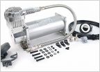 Viair 450c vs ARB ckma12 ... help me decide
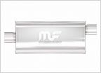 Shopping for Muffler
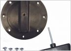 Anyone mount RotoPax to the bedrails?
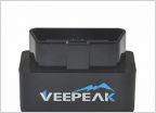 OBD-II Information
 Brake Fluid Flush Questions - 2014 TRD Off-Road
2012 Reverse Camera Switch
Discussion in '2nd Gen. Tacomas (2005-2015)' started by nut, Feb 13, 2012.
Page 5 of 5
Page 5 of 5
Products Discussed in


