

-
Welcome to Tacoma World!
You are currently viewing as a guest! To get full-access, you need to register for a FREE account.
As a registered member, you’ll be able to:- Participate in all Tacoma discussion topics
- Communicate privately with other Tacoma owners from around the world
- Post your own photos in our Members Gallery
- Access all special features of the site
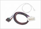 Parts to install for brake controller
 Infamous Ladder Rack Question
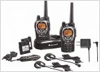 GMRS Radio Newbie
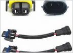 Best LED Replacement Bulbs For 2016-2019 Headlights
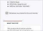 TRD Pro Parts
 Are Joying headunits any good?
2023 Smart Alternator incompatible with DC-DC Charger
Discussion in '3rd Gen. Tacomas (2016-2023)' started by Max8, May 18, 2024.
Page 4 of 5
Page 4 of 5
Products Discussed in


