1. Welcome to Tacoma World!

    You are currently viewing as a guest! To get full-access, you need to register for a FREE account.

    As a registered member, you’ll be able to:
    • Participate in all Tacoma discussion topics
    • Communicate privately with other Tacoma owners from around the world
    • Post your own photos in our Members Gallery
    • Access all special features of the site

2nd Gen Information & Diagnostics

Discussion in '2nd Gen. Tacomas (2005-2015)' started by Dm93, Nov 13, 2022.

  1. Nov 13, 2022 at 8:29 PM
    #1
    Dm93

    Dm93 [OP] Test Don't Guess

    Joined:
    Mar 3, 2015
    Member:
    #150066
    Messages:
    11,719
    Gender:
    Male
    Texas
    Vehicle:
    2014 DC OR 6spd 4x4
    Predator tube steps, Ranch Hand grill guard, Magnaflow CatBack exhaust, Toyota tool box & bed mat, 2LO Module by @Up2NoGood, Rearview Compass/Temp Mirror, Tune by @JustDSM.
    This is kind of a work in progress but I thought I would try to go through some of the electrical & engine systems on the 2nd gen trucks and try my best to explain how they work, and share some methods and tools to diagnose & test them.

    I hope to continue to add to this as I have time and the need arises.
    If you have a question about anything I have posted here just ask and I'll do my best to answer it.

    If you have a specific problem with your truck please create your own thread, include as much information about the problem as you can (be sure to include the year, engine size, and transmission type of the truck) so we can help you.

    If you need a specific wiring diagram, connector/ground/module location, or connector pinout post here or send me a PM and I'll grab it, be sure to include your year, engine size, and transmission type so I can get the correct one.

    Also if you spot any errors in what I have posted or have anything you would like me to add let me know and I'll see what I can do.

    Change Log:
    11/13/22: Initial Thread.
    12/12/22: Added P0500 Description & Diagnostics.
    03/06/23: Added Junction Connector & Harness Joining Connector Pinouts for 05-08
    12/23/23: Updated charging system testing.
    1/1/24: Added some YouTube channel links.
    3/31/24: Added explanation of Recall vs Service Campaign vs TSB
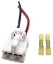
    5/12/24: Added Part Numbers for Blower Motor Connector & Terminals

    Diagnostic Tools & Equipment I Use

    Most of the links I posted is the stuff I actually have and use but some of them are cheaper alternatives that I found.


    A scan tool that can read codes & data from all modules is recommended.
    There's many out there that can do this but not many in the DIY budget, the only ones I currently have experience with are:

    Snapon Verus Pro/Verus Edge (~$1500-4000 Used Ebay) Also has a built in oscilloscope
    Autel MS906BT ($1200 Amazon) There's also other Autel variants with varying degrees of functionality.
    Think Diag ($100 Amazon + ~$70/year for full functionality) Pairs with an Apple or Android smartphone comes with 1 year full coverage.
    Launch x431 Pro 3s+ (~$900-1100 Amazon) There's also other Launch variants with varying degrees of functionality.


    Standard Test Light:
    Preferred over a meter to check power & ground circuits as it at least provides some load where as a meter does not. I also use it at times to check for spark, help locate shorts to ground, triggering relays, and substituting switch inputs.
    My preferred test light is the OTC 3633 Mini but there are cheaper options for a basic test light.


    5 amp test light:
    Used to load a higher current power or ground circuit to verify it can carry a load, also works well in certain situations for finding shorts to ground.
    Can be made with an H11 headlight connector, bulb, & banana jacks


    AC/DC Clamp Meter:
    Used for checking voltage, current, and resistance.
    A basic multimeter can be used for voltage and resistance checks.

    Power Probe Cigarette Lighter Adapter:
    Provides a convenient source of power and ground for interior electrical testing.

    Relay Jumper Set:
    Used to easily test & activate relays in circuit
    Lisle 56840 fits most Toyota relays

    Backprobe set:
    Allows checking voltages at terminals of connectors with them plugged in.

    Piercing Probes:
    Allows checking wires with minimal damage to the insulation (when piercing exterior wires always seal the hole with liquid tape to prevent moisture entry).

    Alligator Clips:
    Mostly used for a meter, test light, or scope to clip to a ground or one of the battery terminals.

    Test Leads With Banana Jacks:
    Used to connect my meter, scope, test light, or other equipment.

    Fuel Pressure Gauge:
    Used to check fuel pressure.

    Injector tester:
    Used along with a fuel pressure gauge to test injector function and balance.

    Terminal Test Kit:
    Used for front probing terminals without damage, checking pin fitment (drag), and other various tests.

    Fuse Saver:
    Useful for shorts instead of wasting fuses.
     
    Last edited: May 12, 2024
    This site contains affiliate links for which the site may be compensated.
    #1
  2. Nov 13, 2022 at 8:30 PM
    #2
    Dm93

    Dm93 [OP] Test Don't Guess

    Joined:
    Mar 3, 2015
    Member:
    #150066
    Messages:
    11,719
    Gender:
    Male
    Texas
    Vehicle:
    2014 DC OR 6spd 4x4
    Predator tube steps, Ranch Hand grill guard, Magnaflow CatBack exhaust, Toyota tool box & bed mat, 2LO Module by @Up2NoGood, Rearview Compass/Temp Mirror, Tune by @JustDSM.
    Helpful Posts, Threads, & Links

    4.0L Scope Captures
    4wd System Operation & Help
    Blower High Speed Relay Mod (Prevent Blower Switch Failure)
    RA60 Transmission Information & Links by @gearcruncher
    R155 Transmission Information & Links by @gearcruncher
    A340 Transmission Information & Links by @gearcruncher
    A750 Transmission Information & Links by @gearcruncher
    Parts Cannon Fails

    YouTube auto diagnostic & repair channels to watch:

    Automotive Diagnostics & Programming: Jake Barnes does mobile diagnostics, programming, some module repair, and EEPROM work.

    ScannerDanner: Paul Danner is an automotive instructor at Rosedale Technical College, he teaches everything from basic electrical to advanced diagnostics and also does live case studies.

    GoTech: Good training and live case studies.

    New Level Auto: Keith Defazio the diagnostic guru of Staten Island mainly posted short diagnostic quickies but has since moved on to other things and doesn't post much anymore.

    South Main Auto: Eric O does everything from general auto repair and tires to complex diagnostics.

    Pine Hollow Auto Diagnostics: Ivan will work on pretty much anything with wheels and an engine, does alot of advanced diagnostics, some vintage vehicle repair, and really likes the "no parts required" fixes.

    Automotive Test Solutions: Bernie Thompson does advanced driveability diagnostics and analyzing waveforms on a scope, he does some showcasing of their equipment but he also diagnoses alot of "unfixable" vehicles that have been kicked around from shop to shop and had a multitude of parts thrown at them.

    Philip Bailey: Does general diagnostics and repair, not alot of advanced stuff.

    WeberAuto: Hybrid drivetrain and automatic transmission training.

    More to come...

    Why you always want to use the wiring harnesses original to the vehicle when replacing the engine:
    https://youtu.be/vB2kfNZz45U?t=2014


    Recall vs Service Campaign/Customer Satisfaction Program vs TSB

    People often confuse recalls with service campaigns/customer satisfaction programs and technical service bulletins (TSBs) so I will try to explain each one.


    Recall:

    A recall is typically for a defect in a vehicle (software or hardware) that could cause a potential increased safety hazard to the vehicle occupants, bystanders, or other motorists.
    The manufacturer must notify the registered owner of the vehicle in the event of a recall.

    There are 2 types of recall:
    1. voluntary (manufacturer discovers a safety issue and voluntarily issues a recall).
    2. mandated by NHTSA (NHTSA receives enough reports about an issue it deems to be a safety concern and leans on the manufacturer to issue a recall).
    Either way recalls are always a no cost to you repair and typically have no expiration.


    Customer Satisfaction Program/Service Campaign:

    A customer satisfaction program/service campaign is typically essentially a voluntary extended warranty on a specific component or system known to the manufacturer to be problematic, these almost always have a time or mileage expiration and may also have other specifics/limitations in order for the vehicle to qualify.
    Manufacturers will typically notify first owners of qualifying vehicles, however subsequent owners my not always get these notices.

    An example of one that often gets confused for a recall is the frame inspection and coating/replacement program for cold climate states.


    Technical Service Bulletin:

    A technical service bulletin (TSB) is an informational document meant for technicians, they can be for literally anything about the vehicle including but not limited to:

    • new or updated repair/diagnostic procedures
    • common problems
    • general information
    • updated fluids
    • specific repair/diagnostic procedures
    • updated parts
    Any repairs or parts associated with them typically fall under the new vehicle warranty only unless specified otherwise.
     
    Last edited: Jun 4, 2024
  3. Nov 13, 2022 at 8:30 PM
    #3
    Dm93

    Dm93 [OP] Test Don't Guess

    Joined:
    Mar 3, 2015
    Member:
    #150066
    Messages:
    11,719
    Gender:
    Male
    Texas
    Vehicle:
    2014 DC OR 6spd 4x4
    Predator tube steps, Ranch Hand grill guard, Magnaflow CatBack exhaust, Toyota tool box & bed mat, 2LO Module by @Up2NoGood, Rearview Compass/Temp Mirror, Tune by @JustDSM.
    Do's and Don'ts when testing

    Always verify your test equipment works before doing each check or you could end up with false positives or negatives.

    When using a generic meter with multiple ports for voltage and resistance testing make sure your black lead is inserted into the Com port and the red lead is inserted into the VmAΩ port.

    When testing at a connector never shove the probes of your meter or test light into the terminals, if you do the terminals will be damaged and result in poor pin contact. Only touch the pins you want to check, if you need to insert something a small needle can be used on larger terminals but it's much better to use dedicated terminal probes (never insert anything that is larger than the male pins into the female terminals of a connector).

    When backprobing a connector take care to not damage it or short across any pins.

    Never cut the insulation of a wire to test it, use a piercing probe. A needle or very sharp meter leads can be used if that's all you have but a piercing probe is best to minimize insulation damage and always make sure to seal up the holes in the insulation with liquid tape to prevent moisture from getting in and corroding the wire.

    When using a meter to check powers and grounds you always want the circuit loaded (whatever you are checking power at plugged in and turned on) or the test is not valid (see the videos below for examples).

    https://www.youtube.com/watch?v=xazvmJ8_p5Q&list=PLuvBuPee2fiCa4B0sgIFry_rtgT-akaNa&index=16&t=25s

    https://www.youtube.com/watch?v=LGts5gWsLOc&list=PLuvBuPee2fiCa4B0sgIFry_rtgT-akaNa&index=14

    Testing Methods

    Finding a Short To Ground on a Wire With a Test Light
    A short to ground can sometimes be easily located with the help of a test light, most of the time I prefer to use the 5 amp test light to locate shorts on fused circuits and the small test light for shorts on signal circuits.

    For a fused circuit first disconnect all the loads from the suspect circuit, connect one end of the test light to battery positive and the other end to the circuit to be tested at the load side of the fuse (sometimes I connect it in place of the fuse).
    If the wire is currently shorted to ground the test light will light, at that point you can wiggle wiring while you watch the test light. When you see the light flicker or go out you are close to your short, at this point you can continue wiggling and/or do a visual inspection to locate the spot where the wire is shorted.
    If the test light is not lit (wire not currently shorted) you can also do the wiggle check and look for the light to flicker, when it does you can narrow in on the location of the short in the same fashion.

    For a signal circuit disconnect the wire at both ends, one end of the test light connected to battery positive connect the other end to the circuit to be tested and perform the same wiggle checks as above while watching for the light to flicker.

    https://www.youtube.com/watch?v=oKCLzf4va7M
     
    Last edited: Dec 26, 2022
  4. Nov 13, 2022 at 8:31 PM
    #4
    Dm93

    Dm93 [OP] Test Don't Guess

    Joined:
    Mar 3, 2015
    Member:
    #150066
    Messages:
    11,719
    Gender:
    Male
    Texas
    Vehicle:
    2014 DC OR 6spd 4x4
    Predator tube steps, Ranch Hand grill guard, Magnaflow CatBack exhaust, Toyota tool box & bed mat, 2LO Module by @Up2NoGood, Rearview Compass/Temp Mirror, Tune by @JustDSM.
    Starting System

    Description & Operation


    The starting system consists of the Ignition Switch, Starter (STA) Relay, Transmission Range Switch (AT) or Clutch Start Switch (MT), Clutch Start Cancel Switch (MT only if equipped), & Starter.
    Power flows from the ALT Fuse (120/140A) to the AM1 Fuse (50A) to Pin 4 (White/Blue) of the Ignition Switch, when the key is turned to the crank position power flows out of the ignition switch on Pin 3 (Black/White) through the STA Fuse (7.5A) through the Transmission Range Switch (AT) or Clutch Start Switch (MT) to Pin 1 of the STA Relay.

    Power also flows from the AM2 Fuse (30A) to Pin 5 (White/Red) of the Ignition Switch, when the key is turned the the crank position power flows out of the Ignition Switch on Pin 7 (Green/Black) to Pin 5 of the STA Relay.

    Pin 2 of the STA Relay is grounded via Ground Point EA on the right front fender and ground point EB on the left front fender.

    When power is applied to Pins 1 & 5 of the STA Relay it closes and sends power to the S terminal on the starter engaging the starter to crank the engine.

    Diagnostics & Testing

    The following tests are assuming the battery is good, the battery voltage can be checked with a meter while cranking (voltage shouldn't drop below about 10v).

    First verify Fuses AM1 (50A), AM2 (30A), & STA (7.5A) in the underhood fuse box are not blown.
    If you have a manual transmission and suspect the clutch switch you can push the clutch start cancel button if you have it, if it starts with that then test the clutch switch to verify it's bad.
    If you have an automatic transmission you can try moving the shifter from park to neutral while holding the key in the crank position, if the truck cranks suspect the transmission range switch.

    The starting circuit is very simple to diagnose with a test light.
    With the test light connected to engine ground and a helper to turn the key to crank:

    1:With the test light connected to engine ground and a helper to turn the key to crank touch the test light to the main power stud of the starter and verify it is lit and stays lit when the key is turned to crank, if it does go to step 2 if it does not go to step 13.

    2: Check that the test light lights on the S terminal (small wire), if it does but the engine does not crank and the starter makes no noises the starter is bad if it does not go to step 3.

    3: Remove the starter relay, connect the test light to battery positive and touch the tip to Pin 2 and verify the light lights. If it does go to step 4, if it does not check ground points EA and EB.

    4: Test light connected to battery positive touch Pin 3 and see if the test light lights, if it does go to step 5 if it does not you need to find the open in the wire going to the starter.

    5: Test light connected to battery negative touch Pin 5, have someone turn the key to crank and verify the light lights. If it does go to step 6 if it does not go to step 7.

    6: Test light connected to battery negative touch Pin 1, have someone turn the key to crank and verify the light lights. If it does then the STA Relay is bad, if it does not go to step 8

    7: Test light connected to ground backprobe Pin 5 White/Red at the ignition switch, verify it lights and stays lit when the the key is turned to crank. If it does go to step 9, if it does not verify power at the AM2 fuse with the test light. If it's good there find and repair the open in the Red/White wire between the AM2 fuse and the ignition switch.

    8: Test light connected to battery negative check both sides of the STA Fuse while someone holds the key in the crank position and verify the light lights, if it does go to step 10 if it doesn't go to step 11.

    9: Test light connected to ground backprobe Pin 7 Green/Black at the Ignition Switch, turn the key to crank and verify the light lights. If it does the Green/Black wire is open between the switch and STA Relay, if it does not then the ignition switch is bad.

    10: (M/T) Test light connected to ground go to the Clutch Start Switch (behind the clutch pedal on the firewall) backprobe pin 1 Blue/Black and verify the light lights when the key is turned to crank, if it does not then find and repair the open in the Blue/Black wire between the clutch switch and STA fuse (note there is also a diode in this circuit). If it does do the same check at Pin 2 Black/Yellow with the switch depressed, if it lights on pin 1 but not pin 2 with the switch depressed then the clutch switch is bad. If it lights on both sides find and repair the open in the Black/Yellow wire between the clutch switch and STA Relay.

    (A/T) Test light connected to ground & transmission in park backprobe Pin 4 (Violet) at the transmission range switch (right side of transmission) verify the light lights when the key is turned to crank, if it does not find and repair the open in the Violet wire between the transmission range switch and STA fuse. If it does then backprobe Pin 5 (Black/Yellow) and do the same check, if it lights on Pin 4 but not on Pin 5 the transmission range switch is bad. If it lights on both pins find and repair the open in the Black/Yellow wire between the transmission range switch and STA Relay.

    11: Test light connected to ground backprobe Pin 4 White/Blue at the ignition switch, verify it lights and stays lit. If it does go to step 12, if it does not verify power at the AM1 fuse with the test light. If it's good there find and repair the open in the White/Blue wire between the AM1 fuse and ignition switch.

    12: Test light connected to ground backprobe Pin 3 (Black/White) at the ignition switch verify the light lights when the key is turned to crank, if it does then find and repair the open in the Black/White wire between the ignition switch and STA fuse. If it doesn't the ignition switch is bad.

    13: Test light connected to battery positive touch the test light to the engine block, verify the light lights and stays lit when the key is turned to crank. If it does find and repair the bad connection in the power wire to the starter, if it does not find and repair the bad block ground.


    Charging System

    Description & Operation

    The Alternator is internally controlled & regulated, charging voltage varies based on temperature and can vary from about 13.2V when it's hot to about 14.8V when it's cold.
    It has 1 main battery wire fed through the ALT Fuse (120A/140A).

    It also has at the connector:
    An ignition input (Battery Voltage with key in Run) on Pin 2 (IG) (Light Green (4.0L) or Pink (2.7L)) from the IG1 No2 Fuse (10A) (4.0L) or IG1 Fuse (10A) (2.7L)
    Voltage sense input (Battery Voltage at all times) on Pin 1 (S) (White) from the ALT-S Fuse 7.5A
    Warning light output on Pin 4 (L) (Grey) Alternator grounds this wire to turn the Battery Warning Light on in the instrument cluster.
    2.7L trucks also have a wire on Pin 3 (M) (Blue) going to the PCM although I'm unsure of it's function.

    Diagnostics & Testing

    Verify the drive belt is in place and tight.
    Verify the ALT-S fuse (7.5A) and IG1 (10A) (2.7L) or IG1 No2 (10A) (4.0L) are not blown.
    Check voltage at the main stud of the alternator engine running, if it is the same as battery voltage proceed to the next step if it is 0v or higher than battery voltage the main ALT fuse is blown or the charge wire is open.

    Check at the alternator connector with a test light key on:
    Test light connected to ground touch Pin 1 (White) and verify it lights, if it does not check both sides of the ALT-S fuse. If the ALT-S fuse has power on both sides find & repair the open in the White wire between the ALT-S fuse and alternator.
    Test light connected to ground touch Pin 2 (Pink 2.7L) (Light Green 4.0L) and verify it lights, if it does not then check both sides of the IG1 Fuse (2.7L) or IG1 No2 Fuse (4.0L). If the fuse has power on both sides but you have no power at the alternator then find and repair the open in the Pink wire (2.7L) or Light Green wire (4.0L).
    If all circuits test good the alternator has failed

    Verify ALT-S Fuse (7.5A) in the engine room fuse box is in place and not blown.

    Key on unplug alternator connector and verify warning light goes out, if it does not check for a short to ground on the L terminal wire (Pin 4 (Grey)).

    Verify Pin 1 (White) at the alternator connector has power at all times, if it does then most likely the regulator is failing in the alternator. If it doesn't then verify power on both sides of the ALT-S Fuse (7.5A), if that's good find and repair the open in the wire between the alternator and engine room fuse box.
     
    Last edited: Dec 23, 2023
    b_r_o, Yota80482, 4x4spiegel and 5 others like this.
  5. Nov 13, 2022 at 8:31 PM
    #5
    Dm93

    Dm93 [OP] Test Don't Guess

    Joined:
    Mar 3, 2015
    Member:
    #150066
    Messages:
    11,719
    Gender:
    Male
    Texas
    Vehicle:
    2014 DC OR 6spd 4x4
    Predator tube steps, Ranch Hand grill guard, Magnaflow CatBack exhaust, Toyota tool box & bed mat, 2LO Module by @Up2NoGood, Rearview Compass/Temp Mirror, Tune by @JustDSM.
    Common Codes

    P030x Misfire

    Many things can cause a misfire, sometimes they can be difficult to diagnose but many times it is simple.
    Oil in the spark plug tubes from a leaking valve cover will swell the coil boots and can cause a misfire.
    A coil boot that is arcing or a carbon tracked plug can cause a misfire.

    Carbon Tracking


    If it's a single cylinder misfire you can swap the plug to a different cylinder and the coil to another cylinder and see if the misfire follows one or the other.
    If it does not further tests such as a compression test and an injector balance test should be done.


    P035x Ignition Coil Primary Circuit


    Description
    Sets when the PCM does not see an Ignition Confirmation (IGF) Signal from the affected coil(s) despite sending an Ignition Timing (IGT) Signal.
    (Note the PCM will disable fuel to the affected cylinder(s) until the fault clears)

    Will cause a misfire when the code is present for the affected cylinder(s) due to the PCM shutting down the fuel injector(s) on the affected cylinder(s).
    If the IGF circuit is open or shorted the truck will be a start/stall, codes p0351-356 will set, and the Check Engine & Trac Off lights will illuminate.
    The IGF circuit should have 5v on it with the key on, it can be checked at any coil on Pin 2 (White/Red) or at J12 or the PCM.

    Diagnostics
    All voltage checks should be done with the key in the run position.

    For a single cylinder code


    First you can swap the coil to another cylinder and see if the code follows, if it does then you have a bad coil if it doesn't proceed to the next step.
    Check for 5v on Pin 2 (White/Red) at the affected coil, if it has 5v there proceed to the next step if 5v is not there you will need to check the wire at J12 (see below)
    Check for power on Pin 1 (Black/Red) preferably with a high current test light, if it's good proceed to the next step if it's not the Black/Red wire is broken somewhere in the harness.
    Check for ground on Pin 4 (White/Black) preferably with a high current test light, if it's good proceed to the next step if it's not the White/Black wire is broken somewhere in the harness.
    If all of the above are good the IGT wire Pin 3 will need to be checked for a short to ground and for continuity to the PCM.

    Codes for all cylinders along with a start/stall
    1: Check for 5v on Pin 2 (White/Red) of one of the coils, if 5v is there proceed to step 2 if it isn't proceed to step 4
    2: Check for power on Pin 1 (Black/Red) of the coil preferably with a high current test light, if it's good proceed to step 3 if not proceed to step 5
    3: Check for ground on Pin 4 (White/Black) of the coil preferably with a high current test light
    4: Unplug the coils one at a time and see if the 5v returns, if it does then the coil you unplugged to get it back is bad if it doesn't return with all the coils unplugged proceed to step 6
    5: Check for power at Connector EA1 Pin 4 (Black/Red) (see picture below).
    6: Find J12 in the interior harness (see pictures below) and check for 5v at Pin 4 (White/Red). If it has 5v there but not at the coils most likely threes a problem in the J12 connector, if not go to step 7.

    7: Unplug J12 and see if the 5v comes back on Pin 4, if it does one of the IGF wires going to the coils is shorted to ground, if it doesn't test the wire between J12 Pin 4 and the PCM for a short to ground or open. If that's fine verify powers and ground at the PCM and if those are good the PCM most likely has failed.

    J12 Location


    P0500 Vehicle Speed Sensor No Signal

    Automatic transmission:
    Sets when the PCM does not receive a speed signal from the Combination Meter (Instrument Cluster) despite receiving a speed signal from the Vehicle Speed Sensor No2 on the transmission.

    Manual Transmission:
    Sets when the PCM does not receive a speed signal from the Combination Meter (Instrument Cluster) despite the engine speed being above 2000 RPM and the engine load indicating the vehicle is being driven.


    Speed sensor signal description & operation:

    Automatic Transmission & 2012-15 Manual Transmission:
    [​IMG]

    The Skid Control ECU (ABS Module) uses the Rear Wheel Speed Sensor signals for vehicle speed & converts the wheel speed signal into a digital signal (aprox 4 pulses per wheel rotation) and transmits it to the Combination Meter (Instrument Cluster). The Combination Meter uses this signal for the speedometer & odometer and then transmits a digital signal (aprox 4 pulses per wheel rotation) out on the SPD terminal to the PCM, TPMS ECU, Inverter (if equipped), Accessory Meter (if equipped), 4wd ECU (if equipped), Radio (09-15 models), Amplifier (09-15 Models with JBL), and the A/C Amplifier (09-15 Models).

    Manual Transmission (05-11):

    The Combination Meter (Instrument Cluster) receives the vehicle speed (aprox 4 pulses per wheel rotation) directly from the Vehicle Speed Sensor on the output shaft of the Transmission (2wd) or the output shaft of the Transfer Case (4wd). The Combination Meter uses this signal for the speedometer & odometer and then transmits a digital signal (aprox 4 pulses per wheel rotation) out on the SPD terminal to the PCM, TPMS ECU, Inverter (if equipped), Accessory Meter (if equipped), 4wd ECU (if equipped), Radio (09-15 models), Amplifier (09-15 Models with JBL), and the A/C Amplifier (09-15 Models).

    SPD circuit:
    Each module on the Speed circuit outputs aprox 5v or 12v on it's SPD terminal which the Combination Meter pulses to ground to indicate vehicle speed, voltage on the SPD circuit will vary depending on what modules the truck is equipped with but should be about 4.7-12v (note the voltage will be 0v key on with the Combination Meter connected).

    Diagnostics
    First verify the following fuses are installed and not blown:
    Gauge (7.5A)
    ECU-B (7.5A)
    IG1 (10A)
    Tests are assuming the Combination Meter (Instrument Cluster) is otherwise functional, if it isn't then diagnose & repair that, clear the codes, and retest for P0500.
    Voltage checks should be done key on engine off with all connectors plugged in unless specified otherwise, key should be turned off before unplugging any connectors. Be aware fault codes may be generated in various modules with connectors unplugged and should be cleared with a scan tool or battery disconnect when testing has been completed. If you need a connector location or wiring diagram for your specific truck post here or send me a PM and I'll get it for you.


    Jb No 2 edit2.jpg


    1: Verify whether or not the speedometer works. If it does go to step 2, if it doesn't go to step 3 (MT 05-11) or 4 (AT & 12-15 MT).

    2: Go to connector PD at the instrument panel J/B no 2 (Behind glovebox left of PCM (see picture)). Backprobe Pin 2 (Violet/White), meter negative connected to ground measure the voltage. If it is less than 4.5v go to step 27, if it is 4.5-12v go to step 22.

    3: Locate the Vehicle Speed Sensor on the Transmission output housing (2wd) or Transfer Case output housing, key on & meter connected to a known good ground check for power (battery voltage) on Pin 1 (Pink). If it has power go to step 5, if it doesn't have power go to step 8.

    4: Scan the ABS module for codes and repair any speed sensor related DTC's, if no codes are present & the ABS warning light goes out with the engine running go to step 10.

    5: Check Pin 2 (White(05-08) White/Green(09-11)) of the vehicle speed sensor for ground (touch meter red lead to Pin 1 (Pink) and black lead to Pin 2 (White(05-08) White/Green(09-11)) , key on (meter should read battery voltage if the ground is good). If the ground is good reconnect the sensor & go to step 16, if it isn't go to step 6.

    6: Go to connector IH1 (Behind Glovebox Black Connector Left of J/B No 2), backprobe Pin 9 (White) and Pin 12 (Yellow). Touch meter leads to Pin 9 and Pin 12, verify the meter reads battery voltage. If it does find and repair the open in the White wire between IH1 and the vehicle speed sensor, if it doesn't go to step 7.

    7: Go to the Combination Meter connector C9 (40 pin), backprobe pin 3 (White(05-08) White/Green(09-11)) and 21 (Violet). connect meter leads between Pin 3 and 21, verify the meter reads battery voltage. If it does find and repair the open in the White wire between the Combination Meter and IH1, if it doesn't then replace the Combination Meter.

    8: Backprobe connector PA Pin 4 (Pink) at the Instrument Panel J/B no 2 (Behind glovebox left of PCM) and check for battery voltage. If voltage is good find and repair the open in the Pink wire between PA and the Vehicle Speed Sensor, if voltage is not good go to step 9

    9: Backprobe connector PF Pin 7 (Pink) at the instrument panel J/B no 2 (Behind glovebox left of PCM (see picture)) and check for battery voltage. If voltage is good at PF Pin 7 but not at PA Pin 4 inspect connectors PA & PF for corrosion and/or burnt pins, if they are good then there is a problem in the junction box. If voltage is not good find and repair the open in the Pink wire between PF and the IG1 Fuse.

    10: Go to connector IA1 (behind left kick panel, topmost connector), backprobe Pin 36 (Red/Yellow). Meter negative connected to ground measure voltage at Pin 36 while driving slowly (or with a rear wheel off the ground, front wheels chocked, and transmission in neutral rotate the wheel by hand (you will need both rear wheels off the ground if you have a limited slip rear axle)), voltage should alternate between 0v and 4.5-12v. If it does but no vehicle speed is being registered on the speedometer replace the Combination Meter, if it doesn't go to step 11.

    11: Meter negative connected to ground, measure voltage at IA1 Pin 36 (Red/Yellow). If it is 4.5-12v go to step 13 if it is less than 4.5v go to step 12.

    12: Unplug the Skid Control ECU (ABS Module), verify the voltage at IA1 Pin 36 (Red/Yellow) goes to 4.5-12v. If it does and vehicle speed registers properly in ABS scan data but no signal is generated as per step 10 replace the Skid Control ECU (ABS Module), if it doesn't go to step 14.

    13: Unplug the Skid Control ECU (ABS Module) and check the voltage on the SP1 terminal (Red/Yellow wire) (pin number varies between year models and module types), if the voltage matches the voltage measured at IA1 in step 11 and vehicle speed registers properly in ABS scan data but no signal is generated as per step 10 replace the Skid Control ECU (ABS Module). If no voltage is present at the SP1 terminal then find and repair the open in the Red/Yellow wire between the Skid Control ECU and connector IA1.

    14: Go the the Combination Meter connector C9 (40 pin), backprobe Pin 6 (Red/Yellow). Meter negative connected to ground measure voltage on Pin 6, if it is 4.5-12v find and repair the open in the Red/Yellow wire between the Combination Meter and IA1. if it is less than 4.5v go to step 15.

    15: With the Skid Control ECU & Combination Meter unplugged test the Red/Yellow wire for a short to ground. If it is shorted to ground find and repair the short to ground, if it isn't replace the Combination Meter.

    16: Go to connector IH1 (Behind Glovebox Black Connector Left of J/B No 2), backprobe Pin 8 (Red/Yellow). Meter negative connected to ground measure voltage at Pin 8 while driving slowly (or with a rear wheel off the ground, front wheels chocked, and transmission in neutral rotate the wheel by hand (you will need both rear wheels off the ground if you have a limited slip rear axle)), voltage should alternate between 0v and 4.5-12v. If it does but no vehicle speed is being registered on the speedometer replace the Combination Meter, if it doesn't go to step 17.

    17: Meter negative connected to ground measure the voltage at IH1 Pin 8 (Red/Yellow). If it is 4.5-12v go to step 19 if it is less than 4.5v go to step 18.

    18: Unplug the Vehicle Speed sensor and verify voltage at IH1 Pin 8 (Red/Yellow) goes to 4.5-12v, if it does but no speed signal is generated when turning the wheel replace the vehicle speed sensor. If it doesn't go to step 20.

    19: Unplug the Vehicle Speed Sensor & measure the voltage between Pin 2 (White) and Pin 3 (Red/Yellow), if the voltage matches the voltage measured in step 17 but no signal is generated as per step 16 replace the Vehicle Speed Sensor. If no voltage is present find & repair the open in the Red/Yellow wire between the Vehicle Speed Sensor and IH1.

    20: Go the the Combination Meter connector C9 (40 pin), backprobe Pin 6 (Red/Yellow). Meter negative connected to ground measure voltage on Pin 6, if it is 4.5-12v find and repair the open in the Red/Yellow wire between the Combination Meter and IH1. if it is less than 4.5v go to step 21.

    21: With the Vehicle Speed Sensor & Combination Meter unplugged test the Red/Yellow wire for a short to ground. If it is shorted to ground find and repair the short to ground, if it isn't replace the Combination Meter.

    22: While still backprobed at connector PD Pin 2 (Violet/White) & meter negative connected to ground measure voltage at Pin 2 while driving slowly (or with a rear wheel off the ground, front wheels chocked, and transmission in neutral rotate the wheel by hand (you will need both rear wheels off the ground if you have a limited slip rear axle)), voltage should alternate between 0v and 4.5-12v. If it does go to step 24, if it doesn't go to step 23.

    23: Go to the Combination Meter connector C9 (40 Pin), backprobe Pin 19 (Violet/White). Meter negative connected to ground measure the voltage at Pin 19, if the voltage matches the voltage measured at PD Pin 2 but no signal is generated when turning the wheel go to step 35. If no voltage is present at C9 Pin 19 but PD Pin 2 has 4.5-12v find and repair the open in the Violet/White wire between the Combination Meter and Connector PD.

    24: Backprobe the SPD terminal (Violet/White)(Pin number varies by year and engine size) at the PCM, meter negative connected to ground measure the voltage at the SPD terminal. Verify the voltage matches the voltage measured at PD Pin 2 in steps 2 & 22, if it does go to step 25. If it doesn't go to step 26.

    25: Connect a scan tool and monitor vehicle speed in the PCM data while driving or turning the wheel, if it remains at 0 despite a signal being generated most likely the SPD circuit in the PCM has failed and the PCM will need to be replaced. If the vehicle speed is working correctly everything is ok at this time and you may have an intermittent problem in which case checks will need to be performed when the problem is present.

    26: Go to J/B No 2 Connector PC, backprobe Pin 12 (Violet/White). Verify the voltage matches the voltage measured at PD Pin 2 in steps 2 & 22, if it does go find and repair the open in the Violet/White wire between Connector PC and the PCM. If voltage does not match PD Pin 2 inspect connectors PD & PC for corrosion and/or burnt pins, if they are good then there is a problem in the junction box.

    27: Backprobe the SPD Terminal (Violet/White)(Pin number varies by year and engine size) at the PCM, meter negative connected to ground measure the voltage at the SPD terminal. If the voltage is less than 4.5v go to step 28, if it is 4.5-12v go to step 29.

    28: While still backprobed at the SPD Terminal (Violet/White) & meter negative connected to ground measure voltage on the SPD Terminal while driving slowly (or with a rear wheel off the ground, front wheels chocked, and transmission in neutral rotate the wheel by hand (you will need both rear wheels off the ground if you have a limited slip rear axle)), voltage should alternate between 0v and 4.5-12v. If it does go to step 25, if it doesn't go to step 30.

    29: Go to J/B No 2 Connector PC, backprobe Pin 12 (Violet/White). Meter negative connected to ground measure the voltage at PC Pin 12. If it is less than 4.5v find & repair the open in the Violet/ White wire between Connector PC and the PCM, if it is 4.5-12v inspect connectors PD & PC for corrosion and/or burnt pins, if they are good then there is a problem in the junction box.

    30: Unplug connector PD, meter negative connected to ground measure voltage at connector PC Pin 12 (Violet/White). If it goes to 4.5-12v with connector PD unplugged go to step 31 (4wd & 2wd w Rear Diff Lock) or 32 (2wd W/O Rear Diff Lock), if not go to step 33.

    31: With Connector PD unplugged measure voltage on Pin 5 (Violet/White), if it's 4.5-12v go to step 32. If it's less than 4.5v unplug the 4wd ECU and test PD Pin 5 Violet/White for a short to ground, if it's shorted to ground find & repair the short. If not reconnect PD, leave the 4wd ECU unplugged, & verify the SPD circuit now works properly, if it does replace the 4wd ECU.

    32: Reconnect Connector PD, go to the Combination Meter, unplug Connector C9 (40 Pin) at the Combination Meter. Verify voltage at Connector PC Pin 12 goes to 4.5-12v, if it does but no signal is generated as per step 28 replace the Combination Meter. If it doesn't find & repair the short to ground on the Violet/White Wire between the Combination Meter and Connector PD.

    33: Determine which module is pulling down the SPD circuit by leaving Connector PD unplugged & unplugging Connectors PF, PE, and PC one at a time (reconnect each one before unplugging the next) in that order while monitoring voltage on PC Pin 12, when the voltage goes back to 4.5-12v go to step 34.

    34: Once you have isolated the connector that is pulling the circuit down figure out which module on that connector is pulling the circuit down by backprobing the SPD Pin for each module on that connector and checking for 4.5-12v, the the connector/module pin list is as follows. All the SPD terminals are Violet/White, if the pin associated with the module in the connector is empty that module SPD Circuit isn't equipped on the truck. Any module reading 0v on the SPD terminal (except the Combination Meter) is suspect, once you determine which module SPD circuit is 0v unplug that module, plug all the other connectors back in and verify the SPD circuit operates normally. If it does then the module you unplugged is likely the culprit, if it doesn't the the SPD wire going to that module is likely shorted to ground.
    PC: Pin 2 A/C Amplifier (09-15) Pin 12 PCM
    PD; Pin2 Combination Meter Pin 5 4wd ECU (if equipped)
    PE: Pin 5 Radio (09-15 Non JBL) Radio Amplifier (09-15 JBL) Pin 13 Inverter (If Equipped), Radio (09-15 JBL).
    PF: Pin 10 TPMS ECU

    35: Connect a scan tool & monitor vehicle speed in the PCM data, connect a test light to a know good ground, touch the tip to Pin 19 (Violet/White). Verify the light doesn't light, if it doesn't go to step 36. If it does then the circuit is shorted to voltage either through a module or a wiring issue, isolate the circuit that is shorted to voltage by unplugging connectors from J/B No 2 as per step 34 until the light goes out. When it does check each module on that connector with the test light, the circuit that lights the light is the suspect circuit. Unplug the module on that circuit and verify the light no longer lights, if it doesn't then that module is bad. If it still does with the module unplugged then find and repair the short to voltage on that circuit.

    36: Tap the test light on and off of Pin 19 while watching vehicle speed on the scan tool and verify vehicle speed changes, if it does replace the Combination Meter. If it doesn't there may be a problem with the PCM.
     
    Last edited: Dec 13, 2022
  6. Nov 13, 2022 at 8:31 PM
    #6
    Dm93

    Dm93 [OP] Test Don't Guess

    Joined:
    Mar 3, 2015
    Member:
    #150066
    Messages:
    11,719
    Gender:
    Male
    Texas
    Vehicle:
    2014 DC OR 6spd 4x4
    Predator tube steps, Ranch Hand grill guard, Magnaflow CatBack exhaust, Toyota tool box & bed mat, 2LO Module by @Up2NoGood, Rearview Compass/Temp Mirror, Tune by @JustDSM.
    HVAC System

    Blower

    Description & Operation

    The blower system consists of the HEATER Fuse (50A), IG1 No2 Fuse (10A), HTR RELAY, Blower Switch, Blower Motor, and Blower Resistor.
    Power flows from the HEATER Fuse (50A) at all times to Pin 5 of the HTR Relay, when the ignition switch is turned to run power flows from the IG1 No2 Fuse (10A) to Pin 1 of the HTR Relay. Ground from ground point IE is supplied to Pin 6 (White/Black) of the blower switch, when the switch is turned on ground is supplied through the switch on Pin 2 (Yellow) to the HTR Relay tuning it on, when the HTR Relay is turned on power from Pin 5 of the relay flows out on Pin 3 (Black/Yellow) through Connector IA4 Pin 8 (Black/Yellow) to Pin 2 (Black/Yellow) of the blower motor.
    Ground to the blower motor is supplied via various paths depending on the selected blower switch position:
    LO: Ground from ground point IE comes directly into the resistor on Pin 1 (White/Black) and out to the blower motor on Pin 2 (White/Blue).
    M1: Ground from Pin 6 (White/Black) of the blower switch is supplied to Pin 7 (Green/Yellow) of the switch into Pin 4 (Green/Yellow) of the resistor and out to the blower motor on Pin 2 (White/Blue)
    M2: Ground from Pin 6 (White/Black) of the blower switch is supplied to Pin 4 (Blue/Black) of the switch into Pin 3 (Blue/Black) of the resistor and out to the blower motor on Pin 2 (White/Blue).
    HI: Ground from Pin 6 (White/Black) of the blower switch is supplied to Pin 3 (White/Blue) of the switch and goes directly to the blower motor.

    The blower resistor contains a non replaceable thermal fuse that will blow if the resistor gets too hot from over-current or insufficient airflow.

    Diagnostics & Testing

    The blower circuit can be easily checked with a test light.


    First verify that the HEATER (50A) and IG1 No2 (10A) fuses are not blown.

    Tests should be done with the key in the run position and blower switch turned to high.
    1: Wiggle the connector at the blower and see if it starts running, if it does replace the blower motor (and connector if melted) if it does not then go to step 2
    2: Test light connected to ground backprobe Pin 2 (Black/Yellow) at the blower motor and verify the light lights, if it does go to step 3 if it does not then go to step 5
    3: Test light connected to battery positive backprobe Pin 1 (White/Blue) at the blower motor and see if the light lights, if it doesn't then go to step 4 if it does then replace the blower motor (and connector if melted).
    4: Test light connected to battery positive access the blower switch connector, backprobe Pin 3 (White/Blue) and see if the light lights. If it does then find and repair the open in the White/Blue wire between the switch and the blower motor, if it does not then replace the blower switch (and connector if melted).
    5: Test light connected to ground touch Pin 5 of the relay socket and verify the light lights, if it does then go to step 6 if it does not then go to step 9
    6: Test light connected to ground touch Pin 1 of the relay socket and verify the light lights, if it does then go to step 7 if it does not then go to step 10
    7: Test light connected to battery positive touch Pin 2 of the relay socket and verify the light lights, if it does then go to step 8 if it does not then go to step 11
    8: Connect a jumper wire from Pin 5 of the relay socket to Pin 3 of the relay socket and verify the blower runs, if it does then replace the HTR Relay if it does not then find and repair the open in the Black/Yellow wire between the HTR Relay and blower motor.
    9: Test light connected to ground remove the HEATER Fuse (50A), touch each terminal and verify the light lights on one of them. If it does then substitute a known good fuse and retest, if it does not then find and repair the open circuit between the HEATER Fuse and ALT Fuse.
    10: Test light connected to ground touch each side of the IG1 No 2 Fuse (10A) and verify the light lights on both sides, if it does the find and repair the open in the Light Green wire between the IG1 No 2 fuse and HTR Relay.
    11: Test light connected to battery positive access the blower switch connector, backbrobe Pin 2 (Yellow) and see if the light lights. If it does then find and repair the open in the Yellow wire between the blower switch and HTR Relay, if it does not then go to step 12.
    12: Test light connected to battery positive backprobe Pin 6 of the blower switch connector and verify the test light lights, if it does then replace the blower switch (and connector if melted) if it doesn't then find and repair the open the the White/Black wire between the blower switch and ground point IE.


    Test should be done with the key in run and the blower switch set to one of the inoperative speeds.
    1: Wiggle the connector at the blower resistor and see if the blower motor operates, if it does replace the blower resistor (and connector if melted) if it does not then go to step 2.
    2: Unplug the resistor connector and verify no pins are melted or burnt, if they are replace the resistor and connector and retest if they aren't then plug it back in and go to step 3.
    3: Test light connected to battery positive backprobe Pin 2 (White/Blue) at the resistor connector and see if the light lights, if it does then find and repair the open in the White/Blue wire between the resistor and blower motor if it does not then go to step 4.
    4: Depending on which speed(s) are inoperative perform the tests below:

    No Low speed: Test light connected to battery positive backprobe Pin 1 (White/Black) at the blower resistor and verify the light lights bright, if it does replace the blower resistor if it doesn't then find and repair the open in the White/Black wire between the blower resistor and ground point IE.
    No Medium 1 speed: Test light connected to battery positive & switch on Medium 1 backprobe Pin 4 (Green/Yellow) at the blower resistor and verify the light lights bright, if it does then replace the blower resistor if it doesn't then got to blower switch tests.
    No Medium 2 speed: Test light connected to battery positive & switch on Medium 2 backprobe Pin 3 (Blue/Black) at the blower resistor and verify the light lights bright, if it does then replace the blower resistor if it doesn't then go to switch tests.
    No High speed but has other speeds: Go to switch tests.

    Switch tests: Access the blower switch connector, test light connected to battery positive backprobe each of the pins with the switch in the corresponding position and verify the light lights bright. If it fails to light bright in one or more positions replace the blower switch (and connector if melted) if it lights correctly in all positions find and repair the open in the corresponding wire(s) between the switch and resistor:
    Low Pin 2 (Yellow)
    Med 1 Pin 7 (Green/Yellow)
    Med 2 Pin 4 (Blue/Black)
    High Pin 3 (White/Blue)

    There have been several updated part numbers for the blower resistor & connector but I believe these are the current ones:
    Resistor: 87138-04070
    Connector: 82141-04Q80

    The wire colors on the updated connector are slightly different as shown below.
    Updated Blower Connector.jpg

    Blower Connector Part Numbers (TW added Amazon links to chineseum connectors not me):

    Connector Housing: 90980-10916
    Terminal (2 required): 82998-12380

    Blend Door Actuators

    Description & Operation
    The 2nd gen blend door actuators are 12v non-feedback type. The Mode and Temperature actuators receive power from the IG1 Fuse (10A) on Pin 4 (Pink) and ground from Ground Point IE on Pin 1 (White/Black), the A/C Control Assembly sends them a 0-12v signal on Pin 2 (Red/White for the Temperature Door & Light Green/Black for the Mode Door) to control their position. The Mode Actuator also sends a signal to the A/C Amplifier on Pin 3 (Green) to force the A/C on when it is in the Defrost or Defrost/Floor position (12v on 05-08 models, 0v on 09-15 models). On 09-15 models the Temperature actuator sends a signal (0v) to the A/C Amplifier on Pin 3 (Brown/White) to force the A/C and Recirculate on when the actuator is in the full cold position.

    The Recirculate Actuator (Air Inlet Servo) is controlled directly by the A/C Amplifier, in fresh air mode the A/C Amplifier sends 12v to Pin 1 (Violet/White) of the actuator and ground to Pin 2 (Pink/Black) of the actuator. In recirculate mode the A/C Amplifier sends ground to Pin 1 (Violet/White) of the actuator and 12v to Pin 2 (Pink/Black) of the actuator.

    Diagnostics & Testing


    The temperature actuator can be seen by removing the glovebox and floor duct, the duct is a little tricky to get off but pretty easy once you figure it out.
    [​IMG]

    The notch on the actuator shaft should line up with the mark on the actuator body as shown in the picture below.
    [​IMG]

    Recirc door should also be open as shown with the recirc button on.

    Closed (Recirc off)
    [​IMG]

    Open (Recirc on)
    [​IMG]


    Meter connected to ground set to volts DC and ignition on, backprobe the connector with a backprobe or other suitable tool such as a needle and check the voltage on the pins:

    Pin 1 (White/Black) (Ground): Should be less than 0.1v at all times
    Pin 2 (Light Green/Black) (Control): should be at 0v with the mode control knob fully counterclockwise and increase linearly to battery voltage as the knob is turned clockwise.
    Pin 3 (Light Green) (Defrost A/C Enable): Should be 0v (05-08 Models) or 12v (09-15 Models) when the mode select switch is on Panel, Panel/Floor, or Floor and change to 12v (05-08 Models) or 0v (09-15 Models) when the knob is in the Floor/Defrost or Defrost position.
    Pin 4 (Pink) (Power): Should be battery voltage at all times.

    If pin voltage is correct but the actuator does not operate remove the actuator and verify the blend door shaft moves freely, if it does then replace the actuator if it doesn't you will have to investigate why the door is stuck.


    Meter connected to ground set to volts DC and ignition on, backprobe the connector with a backprobe or other suitable tool such as a needle and check the voltage on the pins:

    Pin 1 (White/Black) (Ground): Should be less than 0.1v at all times
    Pin 2 (Red/White) (Control): (05-09 Models): Should be at 12v with the temperature control knob fully counterclockwise and decrease linearly to 0v as the knob is turned clockwise.
    (09-15 Models): Should be at 0v with the temperature control knob fully counterclockwise and increase linearly to 12v as the knob is turned clockwise.
    Pin 3 (Brown/White) (Max A/C Enable 09-15 Models Only): Should be 12v when the temperature switch is not in the Max A/C position and change to 0v when it is turned to the Max A/C position.
    Pin 4 (Pink) (Power): Should be battery voltage at all times.

    If pin voltage is correct but the actuator does not operate remove the actuator and verify the blend door shaft moves freely, if it does then replace the actuator if it doesn't you will have to investigate why the door is stuck.


    Meter connected to ground set to volts DC and ignition on, backprobe the connector with a backprobe or other suitable tool such as a needle and check the voltage on the pins:

    Pin 1 (Violet/White) Should be 12v with recirculate turned off and 0v with recirculate turned on.
    Pin 2 (Pink/Black) Should be 0v with recirculate turned off and 12v with recirculate turned off.

    If pin voltage is correct but the actuator does not operate remove the actuator and verify the blend door shaft moves freely, if it does then replace the actuator if it doesn't you will have to investigate why the door is stuck.


    A/C System

    Description & Operation (WIP)

    The A/C control system consists of the HEATER Fuse (50A), IG1 No2 Fuse (10A), HTR RELAY, IG1 Fuse (10A), A/C Fuse (10A), ECU-B Fuse (7.5A), MG CLT Relay, Blower Switch, A/C Control Switch, A/C Amplifier, Evaporator Temperature Sensor (A/C Thermistor No 1), Pressure Switch, PCM, Compressor Clutch, Lock Sensor, & Ambient Air Temp Sensor (09+ only).

    Power flows from the HEATER Fuse (50A) at all times to Pin 5 of the HTR Relay, when the ignition switch is turned to run power flows from the IG1 No2 Fuse (10A) to Pin 1 of the HTR Relay. Ground from ground point IE is supplied to Pin 6 (White/Black) of the blower switch, when the switch is turned on ground is supplied through the switch on Pin 2 (Yellow) to the HTR Relay tuning it on, when the HTR Relay is turned on power from Pin 5 of the relay flows out on Pin 3 (Black/Yellow) through the A/C Fuse (10A) through Connector IA1 Pin 33 (Green/Yellow) to Pin 11 (Green/Yellow) of the A/C Amplifier.

    The A/C Amplifier also receives constant Battery Power on Pin 28 (Red) from the ECU-B Fuse (7.5A) as well as Ignition Power on Pin 14 (Pink) from the IG1 Fuse (10A).
    Ground is supplied to Pin 1 (White/Black) and Pin 14 (White/Black) (V6 only) from Ground Point IE behind the right kick panel.
     
    Last edited: Jun 4, 2024
  7. Nov 13, 2022 at 8:32 PM
    #7
    Dm93

    Dm93 [OP] Test Don't Guess

    Joined:
    Mar 3, 2015
    Member:
    #150066
    Messages:
    11,719
    Gender:
    Male
    Texas
    Vehicle:
    2014 DC OR 6spd 4x4
    Predator tube steps, Ranch Hand grill guard, Magnaflow CatBack exhaust, Toyota tool box & bed mat, 2LO Module by @Up2NoGood, Rearview Compass/Temp Mirror, Tune by @JustDSM.
    Junction Connector & Harness Joining Connector Pinouts (05-08)

    As many of you are aware Toyota does not provide connector pinouts for junction box connectors or harness connectors making it quite tedious to see what circuits are tied together, I have compiled a multi-page spreadsheet that covers each junction connector & harness joining connector in detail including wire colors, circuit descriptions, and internal connections.

    Currently I have only completed one based off the 05-06 wiring diagrams but it should cover up to 08, I'm going to start working on 09-11 and 12-15 when I get time.

    If anyone spots any errors please let me know.

    I also included the stitched together internal circuit diagrams with letters added for each set of connections as well as connector diagrams.


    Engine Room Junction/Fuse Box (Inside engine bay fuse box)

    Inner circuit
    Engine Room JB Inner Circuit Edit.jpg


    Connectors/Fuses
    05-06 Engine Room Fuse Box.jpg

    Interior Relay Box/Driver's Side Junction Box (Left of steering column behind knee bolster).
    I found and corrected a few errors on this one.

    Inner circuit
    Interior Relay Box Inner Circuit Complete Edit.jpg


    Connectors

    Front
    Interior Relay Box Connectors 1.jpg


    Back
    Interior Relay Box Connectors 2.jpg

    Interior Junction Box No 1 (Left kick panel)

    Inner circuit
    05-06 Instrument Panel JB No1 Inner Circuit Edit.jpg


    Connectors
    05-06 Instument Panel JB #1.jpg

    Interior Junction Box No 2 (Behind glovebox left of PCM)

    Inner circuit
    05-06 Instrument Panel JB No2 Inner Circuit1 Edit.jpg


    Connectors (Note it is mounted upside down on the truck)
    05-06 Instrument Panel JB No2.jpg
     

    Attached Files:

    Last edited: Apr 6, 2023
  8. Nov 13, 2022 at 8:32 PM
    #8
    Dm93

    Dm93 [OP] Test Don't Guess

    Joined:
    Mar 3, 2015
    Member:
    #150066
    Messages:
    11,719
    Gender:
    Male
    Texas
    Vehicle:
    2014 DC OR 6spd 4x4
    Predator tube steps, Ranch Hand grill guard, Magnaflow CatBack exhaust, Toyota tool box & bed mat, 2LO Module by @Up2NoGood, Rearview Compass/Temp Mirror, Tune by @JustDSM.
    Reserved for future use.
     
    Last edited: Nov 13, 2022
    tacoJohn35 likes this.
  9. Nov 13, 2022 at 9:05 PM
    #9
    SUMOTNK

    SUMOTNK Pavement Pounder / Mall Crawler

    Joined:
    Sep 8, 2014
    Member:
    #137895
    Messages:
    2,894
    Gender:
    Male
    First Name:
    Eddie
    NorCal/South Bay Area
    Vehicle:
    Looks like a Gen2.5 TRD Sport, but really an '08 TRD OffRoad
    TRD Supercharged / OTT Tuned
    ^^^^This should be a STICKY thread^^^^
     
  10. Nov 16, 2022 at 5:01 PM
    #10
    george3

    george3 Well-Known Member

    Joined:
    Jun 8, 2008
    Member:
    #7173
    Messages:
    4,567
    New Jersey
    Vehicle:
    2008 2.7 Manual Trans Tacoma
    Seat belt beeper, Cabelas (Weathertech) floor liner gray, Covercraft Seat Savers in Taupe, Protecta Heavy Duty Rubber Truck Bed Mat, Pop n Lock PL5200, Pace Edwards Full Metal JackRabbit, Wolverine oil pan heater, Scangauge2, afe pro dry s filter, Remote Underbody 4 Piece LED Light Kit (White) used as Bed light, DIY Washable Cabin Air Filter, PA15-TOY, 4x4 Illuminated Switch, full synthetic, Redline Tuning Hood Support, Smittybilt Nerf Steps black powder-coated
    X2 - hope it happens - a lot of work for the OP and a lot of information.
     
    TnShooter and Dm93[OP] like this.
  11. Nov 20, 2022 at 6:28 PM
    #11
    Dm93

    Dm93 [OP] Test Don't Guess

    Joined:
    Mar 3, 2015
    Member:
    #150066
    Messages:
    11,719
    Gender:
    Male
    Texas
    Vehicle:
    2014 DC OR 6spd 4x4
    Predator tube steps, Ranch Hand grill guard, Magnaflow CatBack exhaust, Toyota tool box & bed mat, 2LO Module by @Up2NoGood, Rearview Compass/Temp Mirror, Tune by @JustDSM.
    Thanks for the compliments :hattip:
     
    Williston and TnShooter like this.
  12. Dec 12, 2022 at 6:27 PM
    #12
    Dm93

    Dm93 [OP] Test Don't Guess

    Joined:
    Mar 3, 2015
    Member:
    #150066
    Messages:
    11,719
    Gender:
    Male
    Texas
    Vehicle:
    2014 DC OR 6spd 4x4
    Predator tube steps, Ranch Hand grill guard, Magnaflow CatBack exhaust, Toyota tool box & bed mat, 2LO Module by @Up2NoGood, Rearview Compass/Temp Mirror, Tune by @JustDSM.
    Added P0500 (Vehicle Speed Sensor Circuit) Information & Diagnostics for anyone interested.
     
    TnShooter likes this.
  13. Jul 12, 2023 at 10:57 AM
    #13
    Socialwork05

    Socialwork05 Active Member

    Joined:
    Jan 27, 2018
    Member:
    #242602
    Messages:
    39
    Gender:
    Male
    Vehicle:
    2011 tacoma 4x4 v6
    2011 tacoma 4x4 TRD, when I press on gas pedal, no stalling on the engine, but when I drive I can feel truck stalling.. I have driven it for 189,000 miles. Can you help. Thanks.
     
  14. Jul 12, 2023 at 1:44 PM
    #14
    TnShooter

    TnShooter The TacomaWorld Stray

    Joined:
    Sep 2, 2010
    Member:
    #42625
    Messages:
    19,954
    Gender:
    Male
    First Name:
    Deogee
    Vehicle:
    07' TRD Off-Road, Auto
    STOCK
    Do you have a check engine light?
    Have you scanned it for codes?

    When does the stalling happen?
    As soon as you start to drive?
    Or when you are already driving, but give it more gas. Like passing some one or speeding up?
     
    SR-71A and Dm93[OP] like this.
  15. Jul 18, 2023 at 11:45 AM
    #15
    Socialwork05

    Socialwork05 Active Member

    Joined:
    Jan 27, 2018
    Member:
    #242602
    Messages:
    39
    Gender:
    Male
    Vehicle:
    2011 tacoma 4x4 v6
    TnShooter
    Engine and Traction light on
    3 techs have not found code
    Engine sounds great and powerful with gas panel all way to floor but stall when driving
    (at times when driving down the block and stop then go, truck seems a smoother drive)
    Thanks for response
     
  16. Jul 18, 2023 at 2:01 PM
    #16
    henryp

    henryp Well-Known Member

    Joined:
    Jan 6, 2012
    Member:
    #70080
    Messages:
    2,377
    Gender:
    Male
    First Name:
    Henry
    Montana
    Vehicle:
    09 DC TRD Off-Road 4x4
    Form follows function
    Bad gas? Bad fuel pump?
     
  17. Jul 18, 2023 at 7:46 PM
    #17
    Dm93

    Dm93 [OP] Test Don't Guess

    Joined:
    Mar 3, 2015
    Member:
    #150066
    Messages:
    11,719
    Gender:
    Male
    Texas
    Vehicle:
    2014 DC OR 6spd 4x4
    Predator tube steps, Ranch Hand grill guard, Magnaflow CatBack exhaust, Toyota tool box & bed mat, 2LO Module by @Up2NoGood, Rearview Compass/Temp Mirror, Tune by @JustDSM.
    I'm not really sure I understand what's going on, is the truck actually stalling as in the engine is turning off or is it just lacking power?
    It idles fine?
    Runs fine at wide open throttle?
     
    SR-71A and TnShooter like this.
  18. Jul 18, 2023 at 7:49 PM
    #18
    TnShooter

    TnShooter The TacomaWorld Stray

    Joined:
    Sep 2, 2010
    Member:
    #42625
    Messages:
    19,954
    Gender:
    Male
    First Name:
    Deogee
    Vehicle:
    07' TRD Off-Road, Auto
    STOCK
    The Engine and Trac light being on, but no codes being found has me at a loss.
    Are all 3 techs at the same shop? Different shops?
    Something isn’t adding up here.
     
    Last edited: Jul 18, 2023
    Dm93[OP] likes this.
  19. Jul 18, 2023 at 7:51 PM
    #19
    Dm93

    Dm93 [OP] Test Don't Guess

    Joined:
    Mar 3, 2015
    Member:
    #150066
    Messages:
    11,719
    Gender:
    Male
    Texas
    Vehicle:
    2014 DC OR 6spd 4x4
    Predator tube steps, Ranch Hand grill guard, Magnaflow CatBack exhaust, Toyota tool box & bed mat, 2LO Module by @Up2NoGood, Rearview Compass/Temp Mirror, Tune by @JustDSM.
    Yea for sure.
     
  20. Aug 13, 2023 at 12:34 PM
    #20
    armyofsquirrels

    armyofsquirrels Embrace the Suck!

    Joined:
    Jul 17, 2012
    Member:
    #82809
    Messages:
    5,250
    Gender:
    Male
    First Name:
    Chip
    Sykesville MD
    Vehicle:
    2015 V6 6Spd Tacoma DCSB Offroad in Pyrite Mica
    See Build Page.
    Awesome job your link is being added to my build page for future references. So detailed!
     
    Dm93[OP] and TnShooter like this.

Products Discussed in

To Top