-
Welcome to Tacoma World!
You are currently viewing as a guest! To get full-access, you need to register for a FREE account.
As a registered member, you’ll be able to:- Participate in all Tacoma discussion topics
- Communicate privately with other Tacoma owners from around the world
- Post your own photos in our Members Gallery
- Access all special features of the site
 Gasket maker for reinstalling timing chain cover
 A Problem with TPMS Compatability
 Can you use the same type of oil for Front / Rear Diff's & Transfer Case
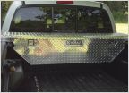 Anyone with UWS box...
2nd gen Tacoma Overhead Compass / Temp Gauge not working
Discussion in '2nd Gen. Tacomas (2005-2015)' started by Scrapla, Nov 20, 2015.