

-
Join 4Runners.com, Our New Toyota 4Runner Forum!
 4Runner Onboard Air
 LED Interior Conversion
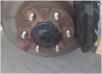 Replacing the Front CV Axle
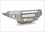
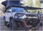 2010+ 4Runner Bumpers & Armor
 2017 4Runner TRD Pro Cement
 Pelfreybilt 4Runner Armor
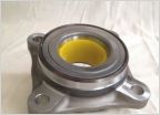 FS: Front Wheel Bearing Assemblies
 4Runners.com Decals Now Available!
 How To: Replace Your 4Runner's Spark Plugs
 Always-On 4Runner Power Outlets
-
Welcome to Tacoma World!
You are currently viewing as a guest! To get full-access, you need to register for a FREE account.
As a registered member, you’ll be able to:- Participate in all Tacoma discussion topics
- Communicate privately with other Tacoma owners from around the world
- Post your own photos in our Members Gallery
- Access all special features of the site
 TWheat40's Build and Adventure Thread
 CattyWampus 4Runner Build Log - With Pan America Dreams
 1999 Supercharged, Limited, Locked Build
 Swimgood's ‘23 TRD Pro Tundra Build
 Hstone556’s DD, don’t mess this one up build thread.
 Y=mx+b's 05 4runner Build Thread
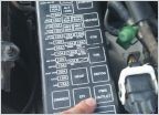
Auxiliary fuse box install (skygear box) -pictures!-
Discussion in '4Runner Builds' started by ramonortiz55, Jun 7, 2015.
Page 1 of 2
Page 1 of 2


