-
Welcome to Tacoma World!
You are currently viewing as a guest! To get full-access, you need to register for a FREE account.
As a registered member, you’ll be able to:- Participate in all Tacoma discussion topics
- Communicate privately with other Tacoma owners from around the world
- Post your own photos in our Members Gallery
- Access all special features of the site
 Flag Pole Hitch Mount
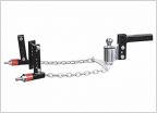 Weight Distribution Hitch Recommendation
 2.7L Alternator differences
 2tr-fe interference or non?!
 ODBII smart phone scanners
Cam gear and chain installation
Discussion in '2nd Gen. Tacomas (2005-2015)' started by foampile, Aug 12, 2015.