

-
Welcome to Tacoma World!
You are currently viewing as a guest! To get full-access, you need to register for a FREE account.
As a registered member, you’ll be able to:- Participate in all Tacoma discussion topics
- Communicate privately with other Tacoma owners from around the world
- Post your own photos in our Members Gallery
- Access all special features of the site
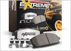 Performance brake pads?
 Tech Stream
 Snorkel alternatives?
 TRD skid plate question
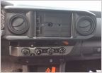 Gen 3 dash iPad mini - radio delete
 3rd gen Access Cab Bed Lights Using Double Cab Cargo Light Switch?
Custom switch panel.
Discussion in '3rd Gen. Tacomas (2016-2023)' started by Idahoffroad, May 22, 2022.


