

-
Welcome to Tacoma World!
You are currently viewing as a guest! To get full-access, you need to register for a FREE account.
As a registered member, you’ll be able to:- Participate in all Tacoma discussion topics
- Communicate privately with other Tacoma owners from around the world
- Post your own photos in our Members Gallery
- Access all special features of the site
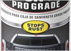 Best spray paint for bumpers/sliders etc
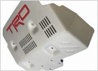 Dealership swears a 4runner Pro skidplate will fit
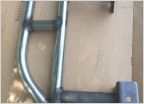 Painting sliders. Quick ?
 Need Recommendations on Skid Plate
 How to remove 1st gen fender flares?
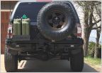 Mud flaps on high clearance rear bumper
DIY Bolt-On Frame Plates for Sliders
Discussion in 'Armor' started by 1 Bored Clerk, Nov 9, 2013.
Page 3 of 31
Page 3 of 31

