

-
Welcome to Tacoma World!
You are currently viewing as a guest! To get full-access, you need to register for a FREE account.
As a registered member, you’ll be able to:- Participate in all Tacoma discussion topics
- Communicate privately with other Tacoma owners from around the world
- Post your own photos in our Members Gallery
- Access all special features of the site
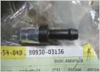 Diff Breather Mod Inquiry
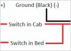 Question: Double Switch DIY Lighting
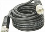 CB Antenna not tuning with Camper Shell
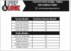 Pop and Lock for 2019 Access Cab
 No radio....need new antenna/ cable
DIY - Build and install a Bussmann RTMR Fuse/Relay Block
Discussion in 'Technical Chat' started by tacozord, Nov 4, 2015.
Page 33 of 70
Page 33 of 70
Products Discussed in


