

-
Welcome to Tacoma World!
You are currently viewing as a guest! To get full-access, you need to register for a FREE account.
As a registered member, you’ll be able to:- Participate in all Tacoma discussion topics
- Communicate privately with other Tacoma owners from around the world
- Post your own photos in our Members Gallery
- Access all special features of the site
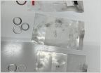 Differentials and transfer case gaskets
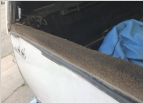 Tailgate Cap
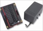 Anyone seen a better deal on a Accessory power module than 450?
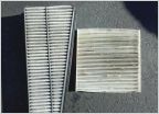 Reminder...Check those filters!!
DIY DASHMOUNT CONTROLLED ALTERNATOR BOOST DIODE CIRCUIT
Discussion in '2nd Gen. Tacomas (2005-2015)' started by Draden, Jan 2, 2023.


