1. Welcome to Tacoma World!

    You are currently viewing as a guest! To get full-access, you need to register for a FREE account.

    As a registered member, you’ll be able to:
    • Participate in all Tacoma discussion topics
    • Communicate privately with other Tacoma owners from around the world
    • Post your own photos in our Members Gallery
    • Access all special features of the site
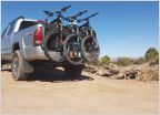
Dome light circuit question

Discussion in '2nd Gen. Tacomas (2005-2015)' started by BH15001, Sep 13, 2010.

  1. Sep 13, 2010 at 6:09 PM
    #1
    BH15001

    BH15001 [OP] Well-Known Member

    Joined:
    Sep 7, 2009
    Member:
    #22375
    Messages:
    59
    Gender:
    Male
    SW PA
    Vehicle:
    09 Tacoma DC LB SR5
    I have a 2009 DC and I would like to wire the light in my cap so that it works with my dome light. Any suggestions as to the easiest way to get to the wire or circuit that goes to my dome light? I had a setup like that on my old Ford and I would like to do the same to this truck.
     
  2. Sep 13, 2010 at 6:47 PM
    #2
    Trap

    Trap Well-Known Member

    Joined:
    May 26, 2010
    Member:
    #37878
    Messages:
    893
    Gender:
    Male
    Vehicle:
    Indego Ink TRD OR
    Electric Tail Gate Lock, EZ Down + Cable Mod, Galvanized Underbody, DK 9000, CloudRider SS Grill insert. BakFlip HD, Cabin Air Filter mod, Alarm, Zero Rust !
    On the drivers side junction box there should be a blue wire in there. That is the interior light. You'll need a meter to confirm it. From there you need to I'd probably power a relay off of that wire to ground. Then wire the relay up to the new light in the cap.

    The box is in the window post at the drivers side door. Actually there is a easier way to find it. It also goes to the fuse box on connector number 1E. There should be a solid blue wire there. It's the bottom right plug. Pin 9 on that connector should be a solid blue wire. Confirm with a meter that it is indeed the interior light. From there tap of that for a relay then run a new fused circuit to the new cap light. Why that way? Cause it will run under the truck a ways so a short is more likely, best keep it separate. Oh and it goes to the body ECU from there so you don't want to load that existing circuit up anymore than it is now so you need a relay.
     
  3. Sep 13, 2010 at 7:10 PM
    #3
    BH15001

    BH15001 [OP] Well-Known Member

    Joined:
    Sep 7, 2009
    Member:
    #22375
    Messages:
    59
    Gender:
    Male
    SW PA
    Vehicle:
    09 Tacoma DC LB SR5
    Thanks Trap
     
  4. Sep 13, 2010 at 10:47 PM
    #4
    joes06tacoma

    joes06tacoma Well-Known Member

    Joined:
    Jan 1, 2010
    Member:
    #28588
    Messages:
    3,185
    Gender:
    Male
    First Name:
    Joe
    Central Coast, CA
    Vehicle:
    06 4x4 Off Road Access Cab v6 6spd
    LEER Shell with dome lights operated with 3 way switches, aux backup lights with relay and 3 position switch, modified wiring to compass/temp display and clock to include switch that disables dimming function (poor man's DRL solution), Scan Gauge 2
    Been there, tried that! I know for sure that a relay won't work powered off the dome light circuit. When the light fades on and off, the relay contacts chatter. There might be a way to wire a small capacitor in to prevent that, not sure. The wire is really thin, not sure it can support another light wired into the existing circuit.
     
  5. Sep 13, 2010 at 11:03 PM
    #5
    Trap

    Trap Well-Known Member

    Joined:
    May 26, 2010
    Member:
    #37878
    Messages:
    893
    Gender:
    Male
    Vehicle:
    Indego Ink TRD OR
    Electric Tail Gate Lock, EZ Down + Cable Mod, Galvanized Underbody, DK 9000, CloudRider SS Grill insert. BakFlip HD, Cabin Air Filter mod, Alarm, Zero Rust !
    No you don't want to wire up another light off of that circuit cause it goes to the ECU. For the dimming part.

    Ok well if it chatters the way to prevent that is use a zener diode inline with the relay coil. The zener diode should be set to 12 volts. that way when the voltage drops below 12 volts the diode will not conduct turning the relay off. Look mom no chatter.

    Forget that it's much more complicated than that. You need a bleed resistor too with the zener so you you need to do some math..

    FORGET THE RELAY !!

    Use this instead:

    http://www.eurothermonline.com/product/SVDD-1V12

    Don't expect it to work unless there is actually a load connected to it. It will not turn on unless there is a load.

    My mistake I should have thought about that damn dimmer part. The blue wire is the positive. so it goes to the trigger positive side the other trigger terminal goes to ground. Then it's just like a normal relay except it's solid state. No chatter.

    Basically you can get these things everywhere at any electronic supply store. You just need it to work DC and have a trigger voltage of 12 volts. The contact side is not as important but it should be able to handle conducting 12 volt no problem,

    Ask them for something like this:

    Continental SSR 12 amp
    0 to 100 VDC load voltage
    4 to 32 VDC control voltage
    1 phase - DC resistive load

    If you try doing it with Zeners or transistors or the thousand other ways of doing it you end up with this thing basically so just use a solid state relay and be done with it.
     
  6. Sep 14, 2010 at 4:07 PM
    #6
    BH15001

    BH15001 [OP] Well-Known Member

    Joined:
    Sep 7, 2009
    Member:
    #22375
    Messages:
    59
    Gender:
    Male
    SW PA
    Vehicle:
    09 Tacoma DC LB SR5
    Thanks again Trap.
     
  7. Sep 14, 2010 at 5:14 PM
    #7
    joes06tacoma

    joes06tacoma Well-Known Member

    Joined:
    Jan 1, 2010
    Member:
    #28588
    Messages:
    3,185
    Gender:
    Male
    First Name:
    Joe
    Central Coast, CA
    Vehicle:
    06 4x4 Off Road Access Cab v6 6spd
    LEER Shell with dome lights operated with 3 way switches, aux backup lights with relay and 3 position switch, modified wiring to compass/temp display and clock to include switch that disables dimming function (poor man's DRL solution), Scan Gauge 2
    I may have to give this another try myself. Thanks Trap!
     
  8. Sep 14, 2010 at 6:22 PM
    #8
    Trap

    Trap Well-Known Member

    Joined:
    May 26, 2010
    Member:
    #37878
    Messages:
    893
    Gender:
    Male
    Vehicle:
    Indego Ink TRD OR
    Electric Tail Gate Lock, EZ Down + Cable Mod, Galvanized Underbody, DK 9000, CloudRider SS Grill insert. BakFlip HD, Cabin Air Filter mod, Alarm, Zero Rust !
    I have about twenty at least of these things in my tool box but there circuit board solder mount so useless for a truck. At least that one has a nice case and wire terminals. If you have some heat sink compound it's a good idea to add some to the bottom when mounting it but chances are just running one light it will not get hot enough anyway. Remember the one I posted the link to is only rated at 12 amps on the load side. Usually they are much larger. Frequency drives use them and sometimes there rated at a 100 amps or more.

    Larger is better if you can pick. 30 amp would be perfect. Would never goof up even when the bulb burned out.

    Just make sure the load side goes down to zero volts and up to at least 24V DC. The trigger is pretty standard 4 to 32 volts cause it's actually a LED. Light turns it on. There is not physical connection between the trigger and the load.
     

Products Discussed in

To Top