

-
Welcome to Tacoma World!
You are currently viewing as a guest! To get full-access, you need to register for a FREE account.
As a registered member, you’ll be able to:- Participate in all Tacoma discussion topics
- Communicate privately with other Tacoma owners from around the world
- Post your own photos in our Members Gallery
- Access all special features of the site
 Suspension strut bushing
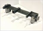 Front-End Hitch Installation
 Fog lights or no fog lights that is the question...
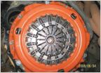 Anybody here replace their clutch or throw out bearing yet?
 Project Fireheadman - 2015 Taco
Gauging valve lashes with shuffled set of lifters
Discussion in '2nd Gen. Tacomas (2005-2015)' started by foampile, Aug 9, 2015.


