

-
Welcome to Tacoma World!
You are currently viewing as a guest! To get full-access, you need to register for a FREE account.
As a registered member, you’ll be able to:- Participate in all Tacoma discussion topics
- Communicate privately with other Tacoma owners from around the world
- Post your own photos in our Members Gallery
- Access all special features of the site
 Gasket For Sealing Under Tracks?
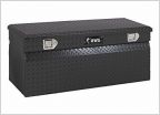 UWS Tool Box with a Shell/topper
 Dome light installation
 Suggestions on a tonneau cover?
 Inside roof bungee net
 Weather Seal for Camper shell rear door
gen2 shell wiring...
Discussion in 'Tonneau Covers, Caps and Shells' started by LeftCoastNerd, Mar 28, 2016.
Page 1 of 2
Page 1 of 2


