

-
Welcome to Tacoma World!
You are currently viewing as a guest! To get full-access, you need to register for a FREE account.
As a registered member, you’ll be able to:- Participate in all Tacoma discussion topics
- Communicate privately with other Tacoma owners from around the world
- Post your own photos in our Members Gallery
- Access all special features of the site
 Duplicolor Color Matched Spray Paint
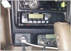 What is a good HAM/CB setup
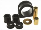 Loose Steering Problem
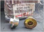 Differential oil
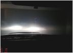 HELP!!!! 2004 Toyota Tacoma Headlight Recommendations
 Steering rack replacement questions
Hard wiring Wet Okole seat heaters: '01-'04 Tacoma
Discussion in '1st Gen. Tacomas (1995-2004)' started by riebe, Aug 25, 2018.

