

-
Welcome to Tacoma World!
You are currently viewing as a guest! To get full-access, you need to register for a FREE account.
As a registered member, you’ll be able to:- Participate in all Tacoma discussion topics
- Communicate privately with other Tacoma owners from around the world
- Post your own photos in our Members Gallery
- Access all special features of the site
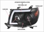 Will the real daytime running light bulb number please stand up?
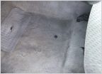 Help finding floor carpet grommets 09 Taco
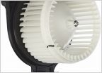 Blower Motor Fan Noise
 Strange noise/oil fixes, but where is the oil going???
 Gas pedal spacer available now! No more shipping cost
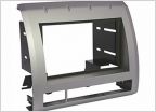 2011 audio upgrade questions
Help Wiring CH4x4 Fog Light switch to Existing Foglight Wires (2013 Tacoma)
Discussion in '2nd Gen. Tacomas (2005-2015)' started by kevinludlow, Sep 22, 2019.
Page 2 of 3
Page 2 of 3


