

-
Welcome to Tacoma World!
You are currently viewing as a guest! To get full-access, you need to register for a FREE account.
As a registered member, you’ll be able to:- Participate in all Tacoma discussion topics
- Communicate privately with other Tacoma owners from around the world
- Post your own photos in our Members Gallery
- Access all special features of the site
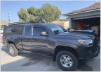 2017 Mud Flaps
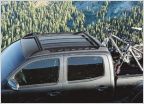 ISO OEM Roof Rack
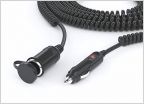 Homemade telescoping rear work/scene/chase light.
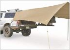 Awning Suggestions
How do you know if a ground connection is right? And how to properly branch circuits?
Discussion in '3rd Gen. Tacomas (2016-2023)' started by Rujack, Jun 29, 2019.
Page 1 of 2
Page 1 of 2


