

-
Welcome to Tacoma World!
You are currently viewing as a guest! To get full-access, you need to register for a FREE account.
As a registered member, you’ll be able to:- Participate in all Tacoma discussion topics
- Communicate privately with other Tacoma owners from around the world
- Post your own photos in our Members Gallery
- Access all special features of the site
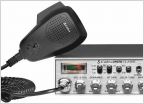 CB Radio info
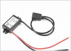 Relocating Dash USB Port
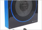 Sub Addition..
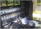 Sub enclosure help
 Amp Install 2013 Tacoma with standard touch screen head unit
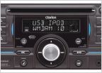 Anyone using this Clarion?
Installing Hidden Satellite Radio Antenna - Pre-Runner
Discussion in 'Audio & Video' started by MD_Taco_Owner, Oct 23, 2016.


