

-
Welcome to Tacoma World!
You are currently viewing as a guest! To get full-access, you need to register for a FREE account.
As a registered member, you’ll be able to:- Participate in all Tacoma discussion topics
- Communicate privately with other Tacoma owners from around the world
- Post your own photos in our Members Gallery
- Access all special features of the site
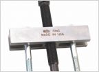 Crank pulley wont pull off
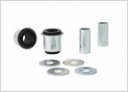 Need old lower control arm bushing's
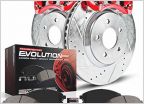 Best brand of brakes for Tundra brake upgrade
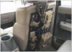 Ogfab molle panel users?
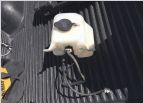 Wiper fluid Res
 Aftermarket Replacement Grilles?
J0hnny Ray's "OEM" Lighting Upgrade
Discussion in '1st Gen. Tacomas (1995-2004)' started by J0hnnyRay, Feb 5, 2022.
Products Discussed in


