

-
Welcome to Tacoma World!
You are currently viewing as a guest! To get full-access, you need to register for a FREE account.
As a registered member, you’ll be able to:- Participate in all Tacoma discussion topics
- Communicate privately with other Tacoma owners from around the world
- Post your own photos in our Members Gallery
- Access all special features of the site
 New Problem with AC/Heater Fan on 2012 Tacoma
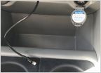 Annoying Problem.
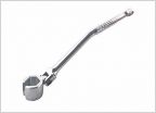 O2 Sensor help.
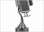 Good iPhone windshield mount. 2011 Tacoma
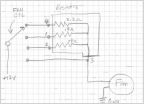
 Help in the fuse box department...
Light bar with existing Fog/driving light switch and High beams
Discussion in '2nd Gen. Tacomas (2005-2015)' started by yzguyfl, Feb 18, 2019.
