

-
Welcome to Tacoma World!
You are currently viewing as a guest! To get full-access, you need to register for a FREE account.
As a registered member, you’ll be able to:- Participate in all Tacoma discussion topics
- Communicate privately with other Tacoma owners from around the world
- Post your own photos in our Members Gallery
- Access all special features of the site
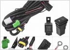 Lighting harness/switch question
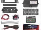 8 Gang Switch Panel - Auxbeam/Amazon
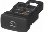 Anzo USA LED Truck Bed Lights install
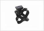 Name of the clamp used to mount Fogs/Driving lights on the tube of a brush guard.
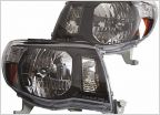 Quick headlight question
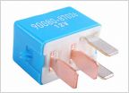 Fog light harness for 4 cylinder?..
Modifying wiring harnesses
Discussion in 'Lighting' started by Jack0928, Jun 19, 2017.
Page 2 of 3
Page 2 of 3


