

-
Welcome to Tacoma World!
You are currently viewing as a guest! To get full-access, you need to register for a FREE account.
As a registered member, you’ll be able to:- Participate in all Tacoma discussion topics
- Communicate privately with other Tacoma owners from around the world
- Post your own photos in our Members Gallery
- Access all special features of the site
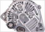 Retrofit DENSO 210-0421 it's a 120 AMP Alternator
 1st gen flat bed
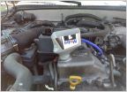 $30gal So I cut the top off
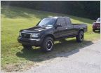 Fog lights for 99 tacoma
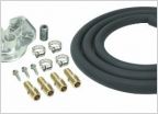 Remote Oil Filter Relocation Kit
 3RZ Noises...
No-Slip HELP!!!
Discussion in '1st Gen. Tacomas (1995-2004)' started by El Taco, Aug 6, 2009.
Page 6 of 7
Page 6 of 7


