-
Welcome to Tacoma World!
You are currently viewing as a guest! To get full-access, you need to register for a FREE account.
As a registered member, you’ll be able to:- Participate in all Tacoma discussion topics
- Communicate privately with other Tacoma owners from around the world
- Post your own photos in our Members Gallery
- Access all special features of the site
 My cab stinks...
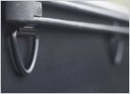 Addition D Rings - Bed Side Alternative Solution
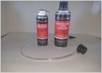
 Is there a product out there that helps restore weather stripping? (The color)
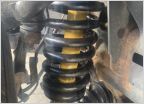 Uca question post lift installation
 TPMS light flashing then solid, no changes to tires
Physical Location of Connector/Junction 2A
Discussion in '2nd Gen. Tacomas (2005-2015)' started by hoffengineering, May 15, 2022.
Page 2 of 2
Page 2 of 2