

-
Welcome to Tacoma World!
You are currently viewing as a guest! To get full-access, you need to register for a FREE account.
As a registered member, you’ll be able to:- Participate in all Tacoma discussion topics
- Communicate privately with other Tacoma owners from around the world
- Post your own photos in our Members Gallery
- Access all special features of the site
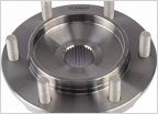 2005 Tacoma front wheel bearing parts?????
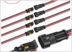 Fog Light Wiring Please Help!
 Intermittent AC blower motor
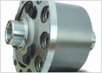 Which TrueTrac fits Tacoma base 2wd??
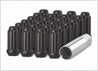 Which type of lug nut do I need to buy?
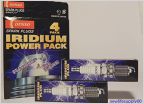 Denso plugs: Which one is best?
Power sliding window mod info thread
Discussion in '2nd Gen. Tacomas (2005-2015)' started by excorcist, Jan 6, 2017.
Page 7 of 13
Page 7 of 13
Products Discussed in


