-
Welcome to Tacoma World!
You are currently viewing as a guest! To get full-access, you need to register for a FREE account.
As a registered member, you’ll be able to:- Participate in all Tacoma discussion topics
- Communicate privately with other Tacoma owners from around the world
- Post your own photos in our Members Gallery
- Access all special features of the site
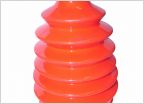 CV Boot, What's Best?
 Arm rest broken - how to fix?
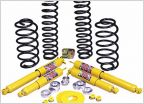 A little lift help - selection and purchase
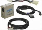 AUX and Ipod cable at the same time?
 Cigarette Lighter popping out of the socket
Quite possibly the worst soldering job for the overhead compass display fix ever
Discussion in '2nd Gen. Tacomas (2005-2015)' started by Wattapunk, Sep 4, 2015.
Page 2 of 3
Page 2 of 3