

-
Welcome to Tacoma World!
You are currently viewing as a guest! To get full-access, you need to register for a FREE account.
As a registered member, you’ll be able to:- Participate in all Tacoma discussion topics
- Communicate privately with other Tacoma owners from around the world
- Post your own photos in our Members Gallery
- Access all special features of the site
 Paquu's build
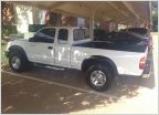 The Life and Times of Lola
 Kooks Mid Travel DC Build and BS Thread
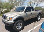 SDHQ Project Gold Member
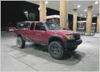 A.smo's '99 Tacoma Build + BS
 The Supracharged King Ranch Bundle of Merriment Build
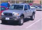
Shortround's '04 Double Cab TRD AT
Discussion in '1st Gen. Builds (1995-2004)' started by shortround13, Apr 1, 2015.
Page 2 of 4
Page 2 of 4


