

-
Welcome to Tacoma World!
You are currently viewing as a guest! To get full-access, you need to register for a FREE account.
As a registered member, you’ll be able to:- Participate in all Tacoma discussion topics
- Communicate privately with other Tacoma owners from around the world
- Post your own photos in our Members Gallery
- Access all special features of the site
 Touch up paint pen?
 TRD Pro Grill mounts?
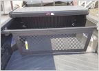 T-nut for factory bed divider rail
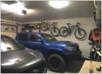 Garage space. How can I use it better?
 Show us your TIP
Wiring help switchpro to ARB compressor
Discussion in '3rd Gen. Tacomas (2016-2023)' started by Glaese, Sep 8, 2024.
Page 1 of 2
Page 1 of 2
Products Discussed in


