

-
Welcome to Tacoma World!
You are currently viewing as a guest! To get full-access, you need to register for a FREE account.
As a registered member, you’ll be able to:- Participate in all Tacoma discussion topics
- Communicate privately with other Tacoma owners from around the world
- Post your own photos in our Members Gallery
- Access all special features of the site
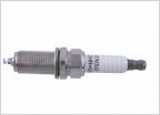 Spark Plugs: 1 GR-FE Can I change only 3?
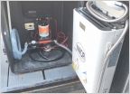 Heated WaterPORT??
 120v Shower/Washdown in Bed
Wiring Up a Relay
Discussion in 'Technical Chat' started by Frogsauce, Jun 20, 2013.


